Control apparatus for an internal combustion engine
a control apparatus and internal combustion engine technology, applied in mechanical apparatus, electric control, machines/engines, etc., can solve the problems of disturbing the air-fuel ratio of the engine, and achieve the effect of improving the driving performance of the engine and the vehicle on which the engine is mounted, and high purifying capacity of the catalys
- Summary
- Abstract
- Description
- Claims
- Application Information
AI Technical Summary
Benefits of technology
Problems solved by technology
Method used
Image
Examples
first embodiment
Structure
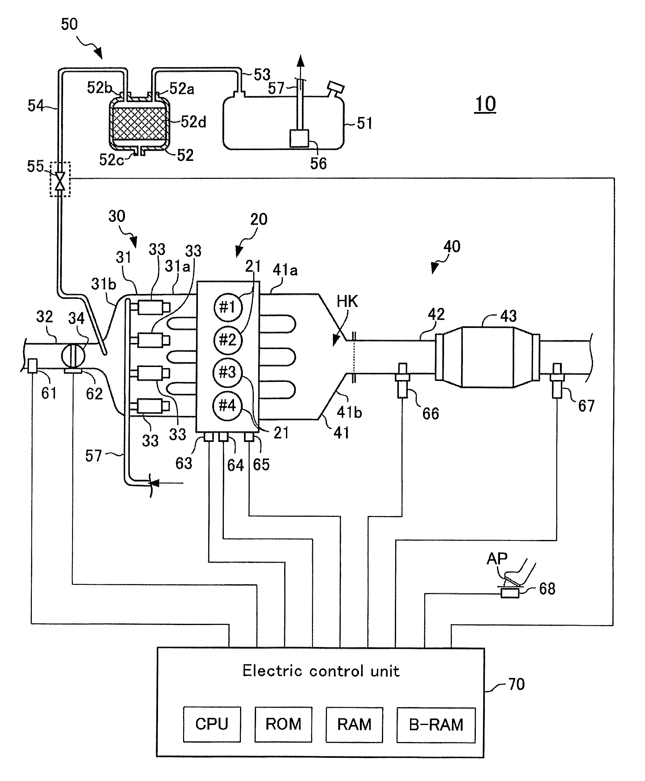
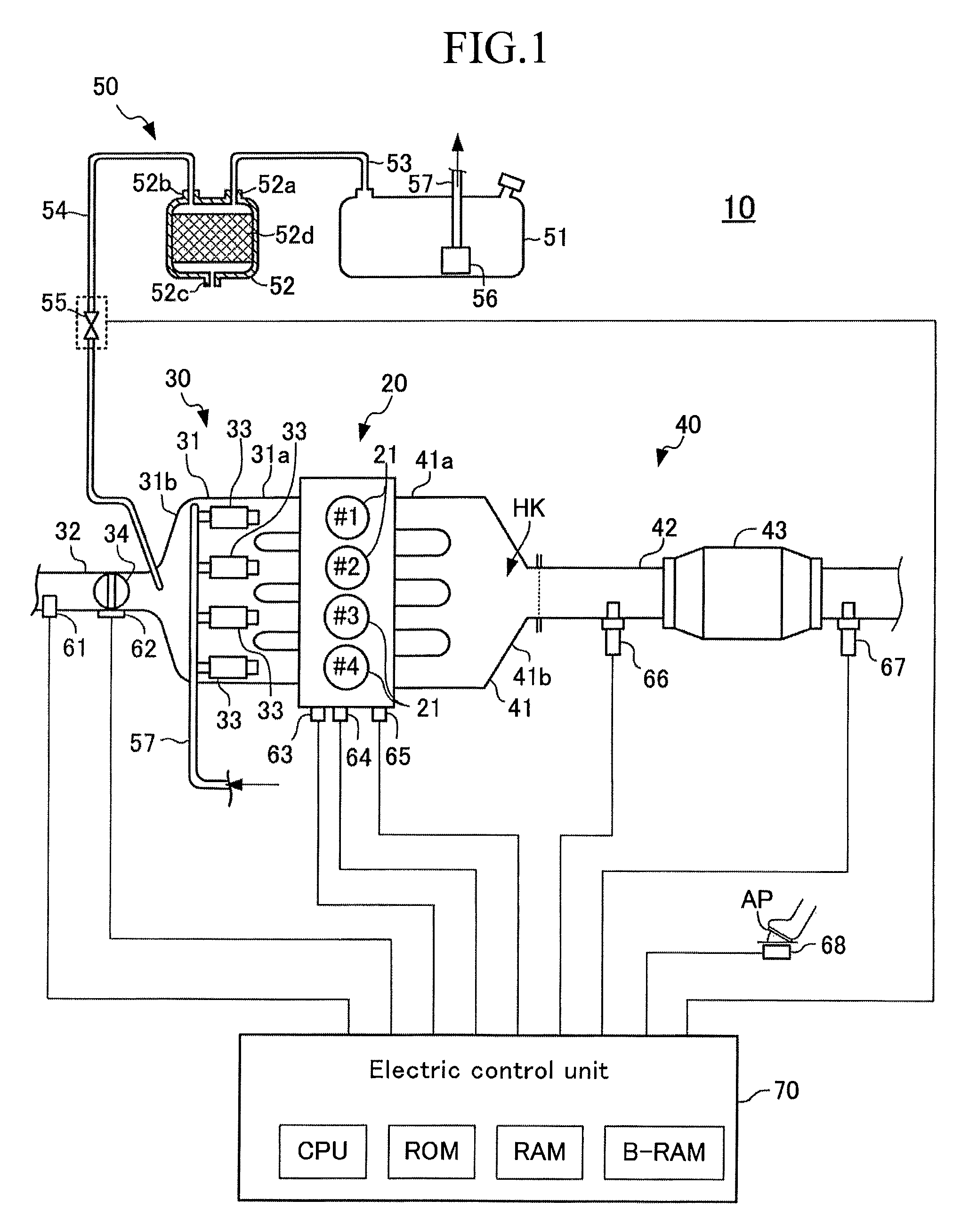
[0053]FIG. 1 schematically shows a configuration of a system in which a control apparatus according to a first embodiment of the present invention (hereinafter, referred to as a “first control apparatus”) is applied to a 4 cycle, spark-ignition, multi-cylinder (in the present example, in-line 4 cylinder), gasoline internal combustion engine 10.
[0054]The engine 10 includes a main body section 20, an intake system 30, an exhaust system 40, and an evaporated fuel supplying system 50.
[0055]The main body section 20 includes a cylinder block section and a cylinder head section. The main body section 20 includes a plurality of cylinders (combustion chambers) 21. Each of the cylinders is communicated with unillustrated “intake ports and the exhaust ports.” A communication portion between the intake port and the combustion chamber is opened and closed by an unillustrated intake valve. A communication portion between the exhaust port and the combustion chamber is opened and closed by...
second embodiment
[0157]Next will be described a control apparatus for an internal combustion engine according to a second embodiment of the present invention (hereinafter, referred to as a “second control apparatus”).
[0158]The second control apparatus is different from the first control apparatus only in that the second control apparatus changes / switches over the condition to start the evaporated fuel purge, based on whether the state of the engine 10 at the purge execution request condition satisfied time point is a first operating state in which the emission is prioritized, or a second operating state in which the drivability is prioritized.
(Actual Operation)
[0159]The CPU of the second control apparatus executes the routines executed by the CPU of the first control apparatus, except the routine shown in FIG. 6. Further, the CPU of the second control apparatus executes an “evaporated fuel purge start control routine shown in FIG. 8 in place of FIG. 6” every time the predetermined time period elapse...
third embodiment
[0175]Next will be described a control apparatus according to a third embodiment of the present invention (hereinafter, referred to as a “third control apparatus”). The third control apparatus is different from the second control apparatus only in “different points 1 and 2” described below.
(The Different Point 1)
[0176]Similarly to the second control apparatus, in the case in which the operating state at the purge execution request condition satisfied time point is the first operating state (in which the emission should be prioritized), the third control apparatus starts the evaporated fuel purge when the target air-fuel ratio abyfr is the target rich air-fuel ratio afRich. Note that, however, even if the operating state at the purge execution request condition satisfied time point is the first operating state and the target air-fuel ratio at that point in time is the target rich air-fuel ratio afRich, the third control apparatus estimates a time period (first time period) from that ...
PUM
 Abstract
Description
Claims
Application Information
 - R&D
- Intellectual Property
- Life Sciences
- Materials
- Tech Scout
- Unparalleled Data Quality
- Higher Quality Content
- 60% Fewer Hallucinations
Browse by: Latest US Patents, China's latest patents, Technical Efficacy Thesaurus, Application Domain, Technology Topic, Popular Technical Reports.
© 2025 PatSnap. All rights reserved.Legal|Privacy policy|Modern Slavery Act Transparency Statement|Sitemap|About US| Contact US: help@patsnap.com


