Arm made of composite material and relative production method

a technology of composite materials and production methods, applied in the direction of water supply installations, cranes, lamination, etc., can solve the problem of negligible generation of a normal force on the main longitudinal axis

Active Publication Date: 2014-11-18
CIFA
View PDF11 Cites 1 Cited by
  • Summary
  • Abstract
  • Description
  • Claims
  • Application Information

AI Technical Summary

Benefits of technology

[0012]According to a characteristic feature of the present invention, the overlapping area between the end of the box-like structure and the mating end of the joint element defines a substantially conical coupling. Substantially conical coupling means, here and hereafter, an area of coupling belonging to a conical or truncated cone surface, in which the ends of the box-like structure and the joint element to be reciprocally glued have profiles which are concordantly inclined at the same angle with respect to the main axis of the articulated segment. This type of coupling allows to increase the overlapping area with respect to the case with no inclination, reducing the tangential stresses which affect the layer of glue interposed between the two ends to be connected, given the same load applied.
[0014]According to a further variant of the present invention, the angle of inclination is comprised between 2.5 and 3.5 degrees. This range is particularly advantageous as it determines an optimal compromise between the overlapping area generated, which should be as big as possible, and the normal force modulus acting on the layer of glue, which should be as low as possible.

Problems solved by technology

On the other hand, a value higher than 5 degrees would imply a considerable increase in the overlapping area, but would have the disadvantage of generating a normal force to the main longitudinal axis not negligible in modulus, tending to separate the parts made of composite material.

Method used


Image

  • Arm made of composite material and relative production method
  • Arm made of composite material and relative production method
  • Arm made of composite material and relative production method

Examples


Embodiment Construction

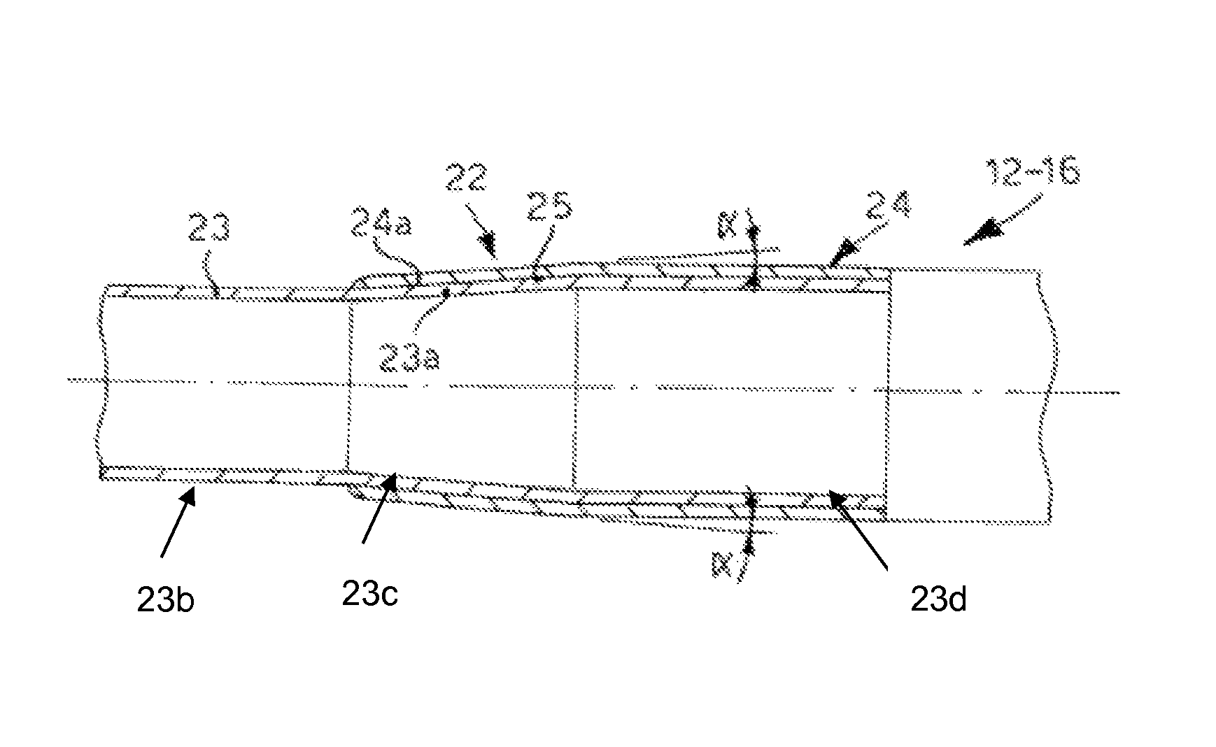
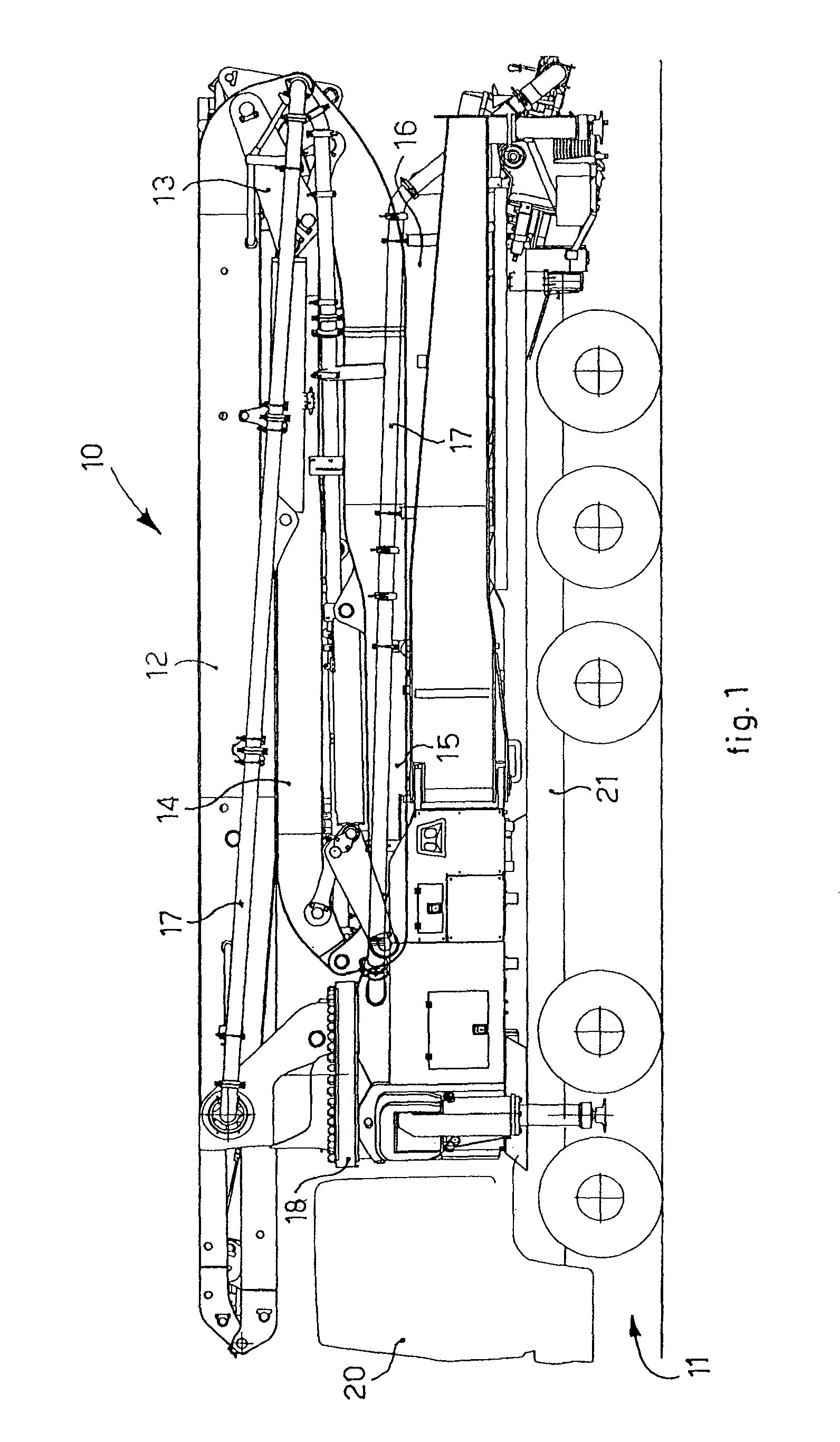
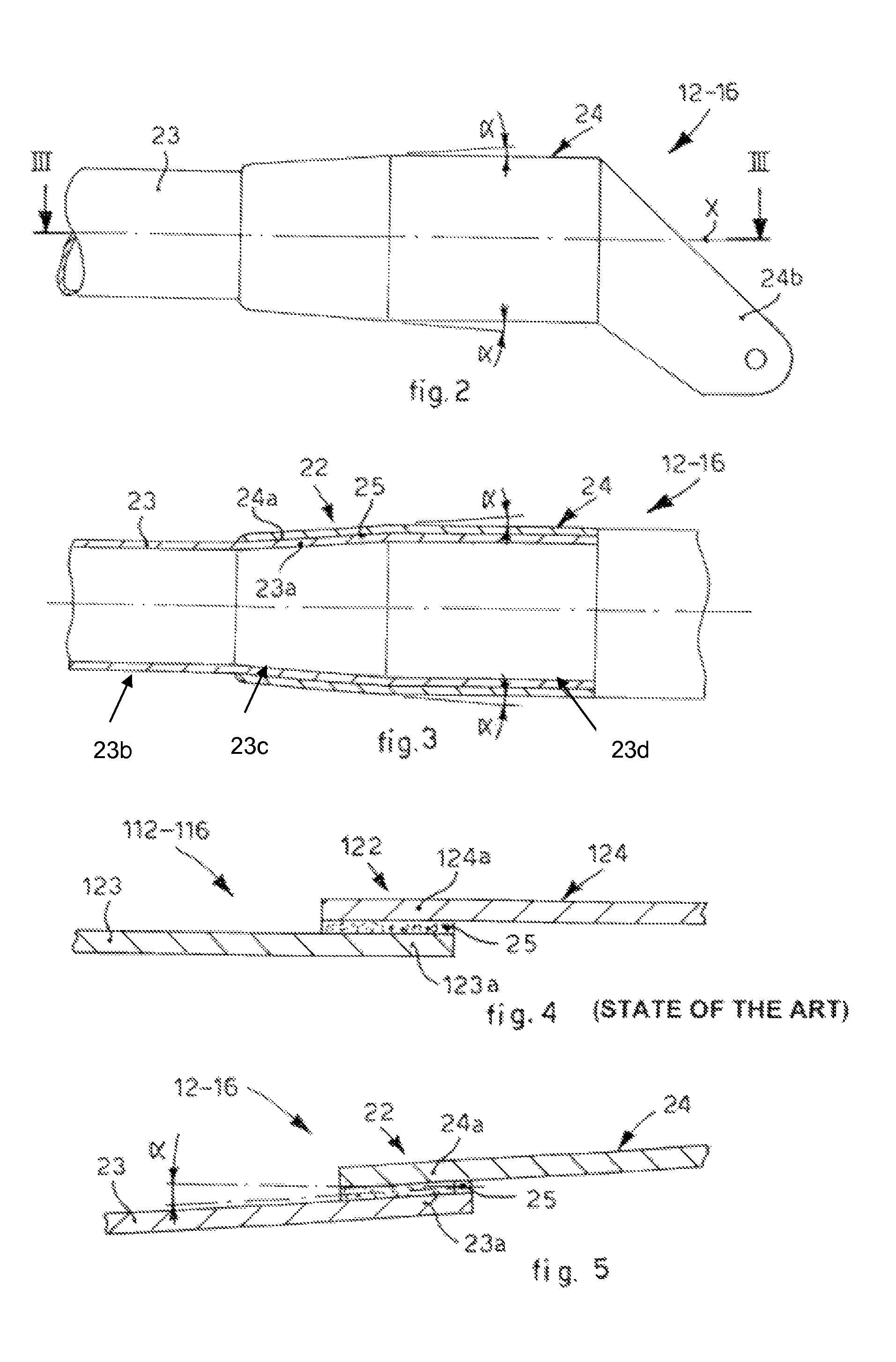
[0021]With reference to FIG. 1, an arm made of composite material 10 according to the present invention, able to distribute concrete or similar material for the building trade, is shown in an assembled position on a heavy work vehicle 11, in a folded position for transport. The heavy vehicle 11 comprises a drive cabin 20 and a support bench 21 on which the arm made of composite material 10 is assembled. The arm 10 according to the present invention comprises a plurality of articulated segments, in this case five, respectively, a first 12, a second 13, a third 14, a fourth 15 and a fifth 16, pivoted with respect to each other at their respective ends. There is also a pipe 17, to feed and discharge the cement. With reference to FIG. 1, the first segment 12, in a known manner, is pivoted to a turret 18, and can be rotated with respect to it. The other segments 13-16 are pivoted in sequence with respect to each other at respective ends and can be driven individually, by means of actuato...


PUM

PropertyMeasurementUnit
angleaaaaaaaaaa
angleaaaaaaaaaa
angleaaaaaaaaaa

Abstract

An arm made of composite material, and relative production method, consisting of a plurality of articulated segments with a longitudinal main axis (x), pivoted to each other, each of the articulated segments comprising a box-like structure and at least a joint element attached thereto by means of gluing, the box-like structure having an end cooperating with an end of the joint element on the inside of the surface of the joint element. The ends define a substantially conical reciprocally overlapping area and have profiles concordantly inclined by an angle (α) with respect to the longitudinal axis (x).

Description

CROSS-REFERENCE TO RELATED APPLICATION[0001]This application claiming the priority of Italian Patent Application No. UD2009A000090 filed on 6 May 2009.FIELD OF THE INVENTION[0002]The present invention concerns an arm made of composite material and the relative production method.[0003]In particular, the present invention is advantageously applied particularly on concrete mixers or the like, and even more particularly in all those cases in which the arms of these vehicles are required to reach large total heights and lengths, and support considerable weights. Advantageously it is preferably applied in the building sector, for the distribution of concrete or other similar material, and it is preferably of the type comprising a plurality of articulated segments pivoted with respect to each other at the ends.BACKGROUND OF THE INVENTION[0004]Heavy work vehicles used in the building sector are known, usually consisting of a truck on which an arm is assembled which has a plurality of articu...

Claims


Application Information

Patent Timeline
Patent Type & Authority Patents(United States)
IPC IPC(8): E03B1/00B66C23/70E04G21/04
CPCE04G21/04B66C23/70Y10T137/8807E04G21/0436
Inventor CORTELLINI, MAURO MARCOMAINI, PAOLO DARIOBERNASCONI, ANDREABERETTA, STEFANO
Owner CIFA
Why Eureka
Try Eureka