
Wireless base station, core network device, wireless communication system, and wireless communication method

Active Publication Date: 2018-01-25
NEC CORP
View PDF3 Cites 0 Cited by
  • Summary
  • Abstract
  • Description
  • Claims
  • Application Information

AI Technical Summary

Benefits of technology

This patent text describes how to improve the coverage of a wireless network by increasing the area where a cell of a base station overlaps with a cell of another base station. This can be done by narrowing the range of the cells or reducing the power of the base station. The technical effect of this is that it can improve network coverage and make it more reliable.

Problems solved by technology

In addition, the wireless base station narrows the cell range (or reduces the transmission power) in some cases, not limited to when carrying out a reset.
However, in the case where a wireless base station narrows the cell range (or reduces the transmission power), various problems can occur.
If the wireless base station reduces the transmission power in the circumstances where a wireless terminal is located in such an area, that wireless terminal cannot be handed over to the adjacent wireless base station, and thereby a call disconnection occurs.

Method used


Image

  • Wireless base station, core network device, wireless communication system, and wireless communication method
  • Wireless base station, core network device, wireless communication system, and wireless communication method
  • Wireless base station, core network device, wireless communication system, and wireless communication method

Examples


first exemplary embodiment

(1) First Exemplary Embodiment

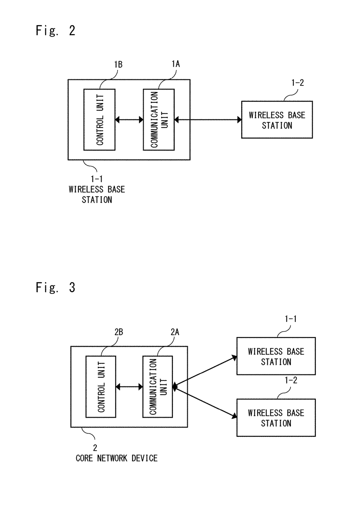
[0036]FIG. 2 shows a configuration example of a wireless communication system according to this exemplary embodiment. The wireless communication system according to this exemplary embodiment includes a wireless base station (first wireless base station) 1-1 and a wireless base station (second wireless base station) 1-2, which is an adjacent wireless base station adjacent to the wireless base station 1-1. The wireless base station 1-1 includes a communication unit 1A and a control unit 1B. Because this exemplary embodiment is characterized by the configuration of the wireless base station 1-1, the description of the configuration of the wireless base station 1-2 is omitted.

[0037]The communication unit 1A is a part that communicates with the wireless base station 1-2. In the case where the wireless base station 1-1 narrows the cell range (or reduces the transmission power), the control unit 1B transmits, to the wireless base station 1-2 through the commun...

second exemplary embodiment

(2) Second Exemplary Embodiment

[0039]FIG. 3 shows a configuration example of a wireless communication system according to this exemplary embodiment. The wireless communication system according to this exemplary embodiment includes a wireless base station (first wireless base station) 1-1, a wireless base station (second wireless base station) 1-2, which is an adjacent wireless base station adjacent to the wireless base station 1-1, and a core network device 2 that is placed in a core network. The core network device 2 includes a communication unit 2A and a control unit 2B. Because this exemplary embodiment is characterized by the configuration of the core network device 2, the description of the configuration of the wireless base stations 1-1 and 1-2 is omitted.

[0040]The communication unit 2A is a part that communicates with the wireless base stations 1-1 and 1-2. For example, the communication unit 2A receives a notification signal that gives a notification that the wireless base s...

third exemplary embodiment

(3) Third Exemplary Embodiment

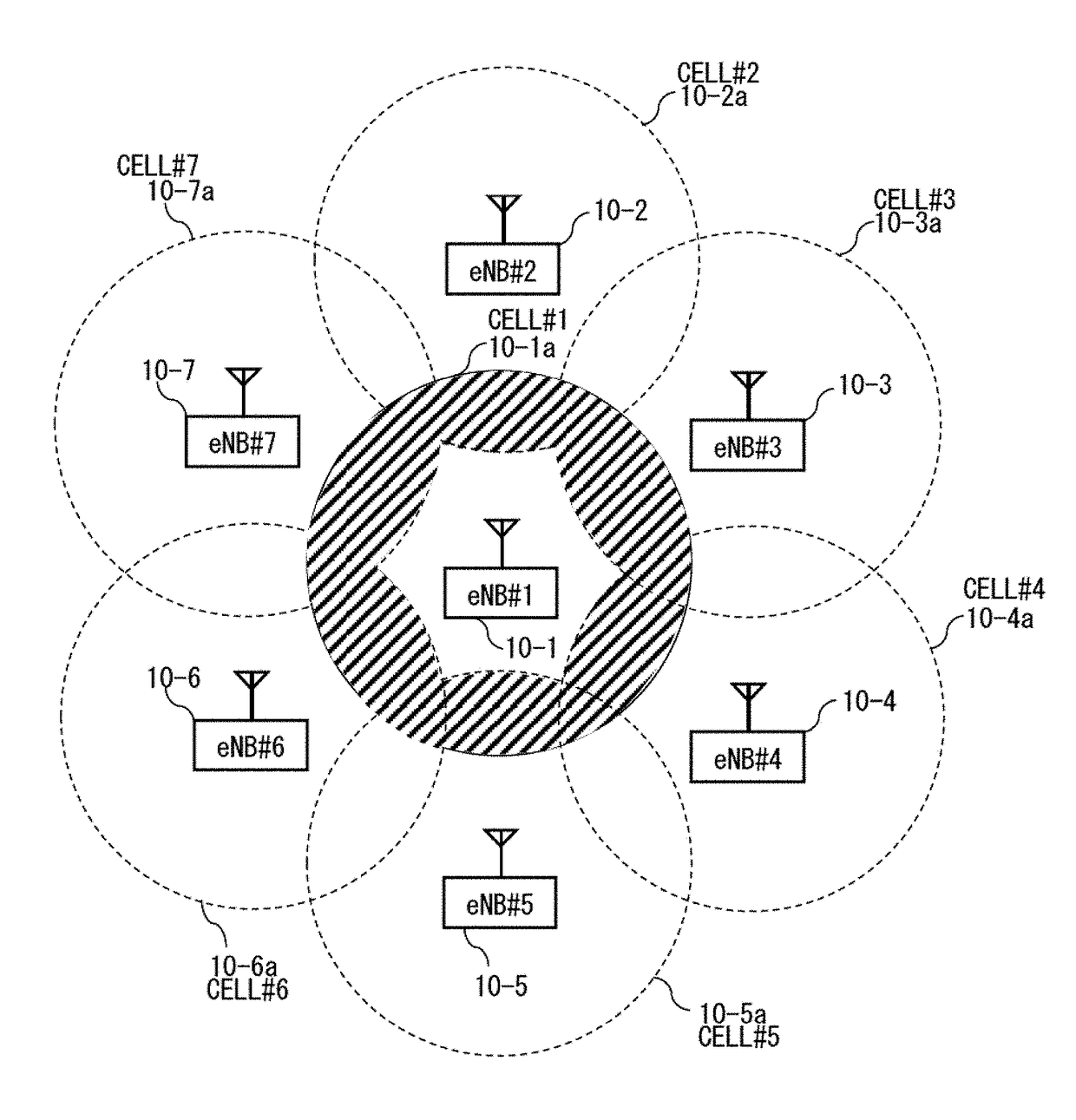
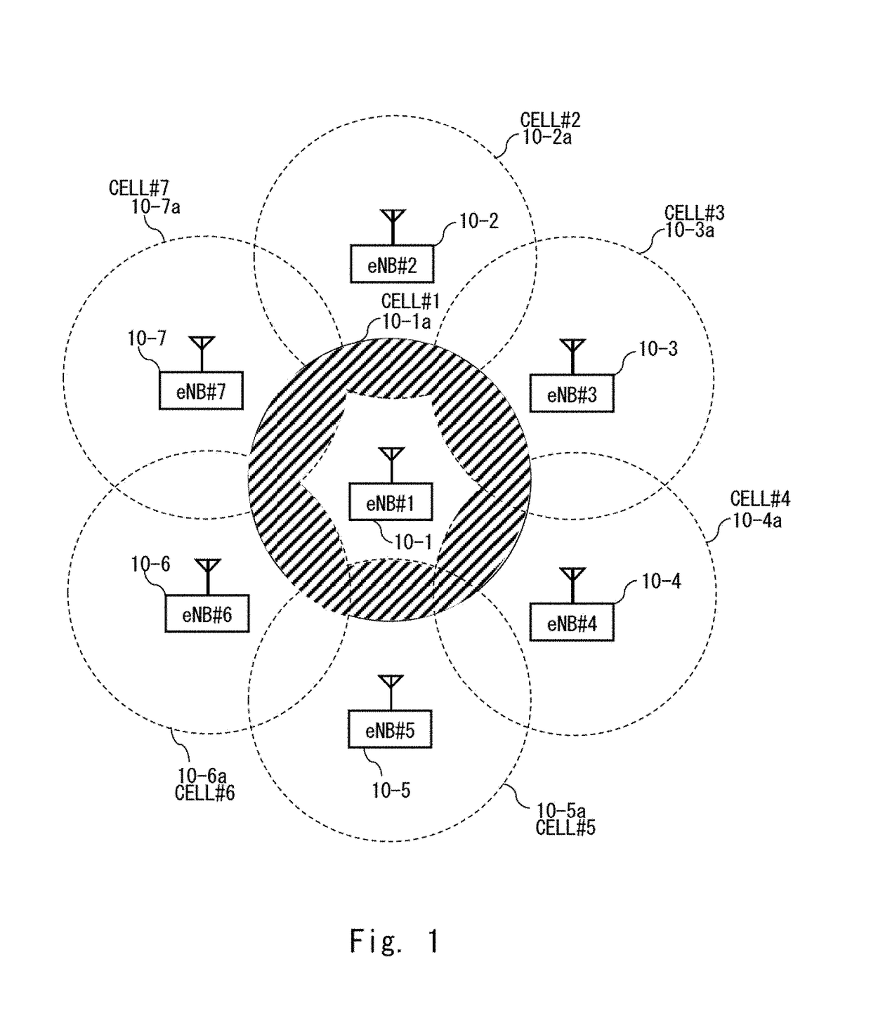
[0042]This exemplary embodiment is an example in which the wireless communication system according to the first exemplary embodiment is applied to an LTE wireless communication system. FIG. 4 shows a network configuration example of an LTE wireless communication system according to this exemplary embodiment. The LTE wireless communication system shown in FIG. 4 is composed of an E-UTRAN (Evolved Universal Terrestrial Radio Network) 110, which is a wireless network, and an EPC (Evolved Packet Core) 210, which is a core network. The EPC 210 includes an MME (Mobility Management Entity) 20 that handles the control plane for network control, a S-GW (Serving Gateway) 21 that handles the user plane for user data, and a P-GW (Packet data network Gateway) 22 for connection to an external network such as the Internet. Note that the MME 20 is an example of the core network device. Further, the E-UTRAN 110 includes a plurality of eNBs (#1-#3) 10-1 to 10-3. The plur...


PUM


Abstract

Provided is a wireless base station capable of increasing an area of overlap between a cell of the wireless base station and a cell of an adjacent wireless base station before the wireless base station narrows a cell range or reduces transmission power. A wireless base station (1-1) includes a communication unit (1A) and a control unit (1B) that transmits, to a wireless base station (1-2) adjacent to the wireless base station (1-1), through the communication unit (1A), an instruction signal that gives an instruction to expand a cell range of the wireless base station (1-2) in a direction of the wireless base station (1-1) before the wireless base station (1-1) narrows a cell range or reduces transmission power.

Description

TECHNICAL FIELD[0001]The present invention relates to a wireless base station, a core network device, a wireless communication system, and a wireless communication method.BACKGROUND ART[0002]Wireless communication networks using wireless terminals and wireless base stations have become widespread, and communication services that allow a wireless terminal to perform wireless communication anytime, anywhere and with anyone are provided today. Further, because the contents of communication services evolve day by day, a wireless base station needs to update software according to need. At this time, the wireless base station carries out a reset. Further, in the event of a defect occurring while providing a communication service, the wireless base station carries out a reset in order to clear this condition in some cases. When the wireless base station carries out a reset, it narrows the cell range (a cell is the range reached a radio wave of the wireless base station) (or reduces the tra...

Claims


Application Information

Patent Timeline
IPC IPC(8): H04W16/08H04W52/40H04W52/34
CPCH04W16/08H04W52/34H04W52/40H04W76/06
Inventor FURUYA, TOMOKI
Owner NEC CORP
Learn More