
Safety-enhanced laser array

Active Publication Date: 2016-09-22
ORACLE INT CORP
View PDF8 Cites 4 Cited by
  • Summary
  • Abstract
  • Description
  • Claims
  • Application Information

AI Technical Summary

Benefits of technology

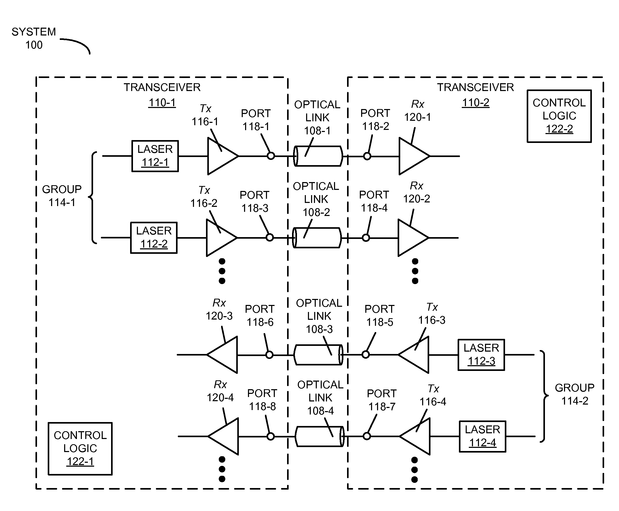
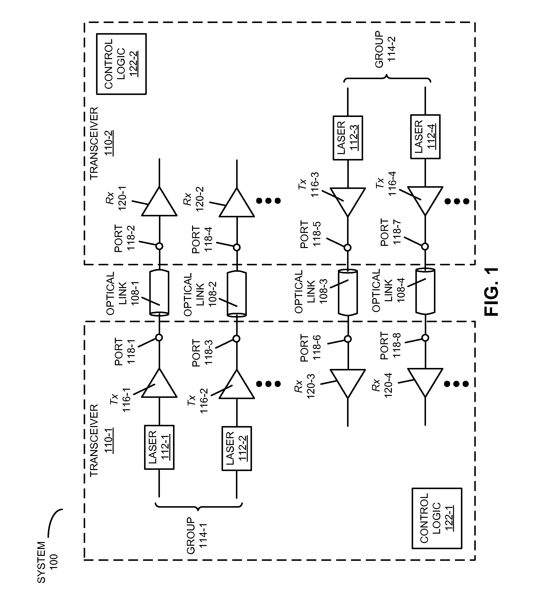
The present patent provides a transceiver system with multiple groups of lasers arranged in a specific pattern. Each group of lasers includes a specific number of lasers, and there are also individual lasers within each group. The system also includes ports that are optically connected to the lasers and receivers to detect and receive optical signals. The control logic of the system can activate or deactivate specific lasers in a given group based on the status of the associated ports. This allows for the independent control of each group of lasers. The lasers may include vertical-cavity surface-emitting lasers (VCSELs) or silicon photonic modulators. The system can maintain Class 1 conditions on the ports and can also transmit optical signals periodically. The N lasers correspond to N independent channels, and the system can detect the loss of signal by analyzing the absence of valid communication during a time interval. The system can also include a processor and memory to execute the program module. The technical effect of the patent is to provide a system with efficient and flexible optical coupling for high-speed data transmission.

Problems solved by technology

In particular, the transmit power is typically dictated by the required optical power at the receiver and the associated loss of the optical link.
While such optical interconnect components are useful for transferring information and can be critical to the performance of the system, these optical interconnects also raise laser-safety concerns, specifically, the eye hazards associated with the use of such laser arrays.
The primary laser-radiation hazard associated with VCSELs is caused by thermal effects that can cause injury to the eye.
The low divergence angle of such laser light, particularly when used with focusing / collimating lens-based optical couplers (such as those included in low-cost, parallel optical-fiber connector assemblies) may pose a threat because the laser light can cause permanent damage within a fraction of a second (i.e., faster than the blink of an eye).
This increases the risk because this invisibility reduces the efficacy of the natural eye response (the human body's protective blink reflex is only responsive to visible radiation).
Therefore, even relatively small levels of laser power per VCSEL in the near-infrared can simultaneously couple into the eye, and can cause high-intensity heating of the human retina, potentially resulting in permanent damage.
Furthermore, detecting the loss of signal may include an absence of the valid communication during a time interval.

Method used


Image

  • Safety-enhanced laser array
  • Safety-enhanced laser array
  • Safety-enhanced laser array

Examples


Embodiment Construction

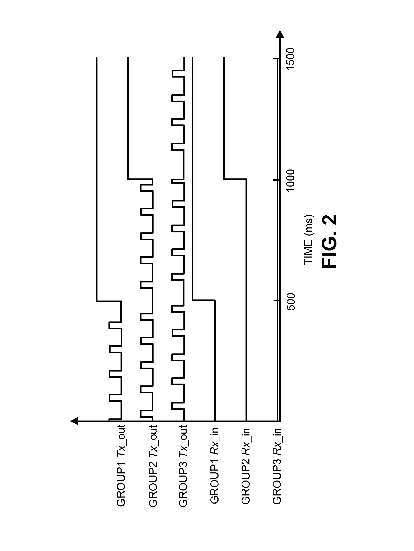
[0026]Embodiments of a transceiver, a system that includes the transceiver, and a technique for ensuring Class 1 conditions for the transceiver are described. When an unsafe port with a loss of signal is detected, the transceiver may enable one laser in a group of lasers associated with the unsafe port and may disable the remaining lasers. Then, the transceiver may instruct a transmitter associated with the one laser to transmit an optical signal on the unsafe port using a reduced transmit power that is less than a threshold value associated with the Class 1 conditions and at a different time than enabled lasers in other groups of lasers. Alternatively, for a safe port on which valid communication is received, the transceiver may enable lasers in a group of lasers associated with the safe port. Then, the transceiver may instruct transmitters associated with the lasers in this group of lasers to transmit optical signals on the safe port using a normal transmit power for the lasers th...


PUM


Abstract

When an unsafe port with a loss of signal is detected, a transceiver may enable one laser in a group of lasers associated with the unsafe port and may disable the remaining lasers. Then, the transceiver may instruct a transmitter associated with the one laser to transmit an optical signal on the unsafe port using a reduced transmit power that is less than a threshold value associated with the Class 1 conditions and at a different time than enabled lasers in other groups of lasers. Alternatively, for a safe port on which valid communication is received, the transceiver may enable lasers in a group of lasers associated with the safe port. Then, the transceiver may instruct transmitters associated with the lasers in this group of lasers to transmit optical signals on the safe port using a normal transmit power for the lasers that is greater than the threshold value.

Description

RELATED APPLICATION[0001]This application claims priority under 35 U.S.C. §119 to U.S. Provisional Application No. 62 / 136,211, entitled “Laser-Array Transmitter Safety Enhancement using Cyclic Quad Bring-Up,” by Patrick Decker, Ashok V. Krishnamoorthy, Xuezhe Zheng, and Ola Torudbakken, filed 20 Mar. 2015 (Atty. Docket No.: ORA15-0931-US-PSP), the contents of which are herein incorporated by reference in their entirety.BACKGROUND[0002]1. Field[0003]The present disclosure relates to techniques for communicating optical signals. More specifically, the present disclosure relates to a transceiver that cycles through groups of lasers having open ports and / or uses reduced transmit power to ensure safe operation.[0004]2. Related Art[0005]Parallel optical interconnects are widely used in board-to-board, rack-to-rack and box-to-box interconnect applications. In these applications, optical transceivers have aggregate capacity from 40 Gigabits per second to over 300 Gigabits per second. Typica...

Claims


Application Information

Patent Timeline
IPC IPC(8): H04B10/03H04B10/564H04B10/50
CPCH04B10/03H04B10/564H04B10/503H04B10/40H04B10/801H04B2210/08
Inventor DECKER, PATRICK J.KRISHNAMOORTHY, ASHOK V.ZHENG, XUEZHETORUDBAKKEN, OLA
Owner ORACLE INT CORP
Learn More