
Variable position anchor assembly for adjusting brake shoes in a drum brake

a technology of brake shoe and variable position, which is applied in the direction of drum brakes, slack adjusters, mechanical equipment, etc., can solve the problems of reducing the service life of the brake shoe lining and the drum, affecting the service life of the brake shoe, and requiring costly and time-consuming maintenance operations to replace the lining. , to achieve the effect of reducing the operating cost of the vehicle fleet, reducing the range of adjustment, and thickening the brake lining

Inactive Publication Date: 2014-11-18
BENDIKS SPAJSER FAUNDEJSHN BREJK LLK
View PDF23 Cites 7 Cited by
  • Summary
  • Abstract
  • Description
  • Claims
  • Application Information

AI Technical Summary

Benefits of technology

The present invention provides an anchor assembly with a means to adjust the position of brake shoes to account for wear in the brakes. This assembly offers better control and finer adjustments than conventional slack adjusters. It also allows for a two-way adjustment of the brake shoes, retracting them from the braking surface if the fit becomes too tight. A motor is used to rotate the adjustifier shafts, allowing accurate control of the gap between the brake shoes and braking surface and facilitating the use of thicker brake linings, which result in longer life of the brakes and reduced operating costs for vehicle fleets. The assembly also integrates with the brake spider for easy manufacture and assembly.

Problems solved by technology

Over time the clearance between the brake shoes and the braking surface of the drum increases with wear of the brake shoe linings and drum.
The increase in clearance leads to a degradation in braking performance and ultimately requires costly and time consuming maintenance operations to replace the linings.
Flexure and sometimes poor fit between the various components located between the slack adjuster and the lining / drum surfaces can result in non-optimum adjustment (either under adjustment or over adjustment).
Second, conventional slack adjusters are typically “one way” in that they are only designed to reduce the clearance between the brake linings and drum and do not “back up” if the lining swells or other factors cause too tight of a fit between the lining and drum surfaces.
For example, while a vehicle descends along a long grade, the brakes heat up causing expansion of the drum.
When the vehicle reaches the bottom of the grade and the brakes cool, however, the drum—and the gap between the drum and brake linings—shrinks which can result in a gap that is smaller than desired and can even result in undesirable contact between the braking linings and drum (a dragging brake).

Method used


Image

  • Variable position anchor assembly for adjusting brake shoes in a drum brake
  • Variable position anchor assembly for adjusting brake shoes in a drum brake
  • Variable position anchor assembly for adjusting brake shoes in a drum brake

Examples


Embodiment Construction

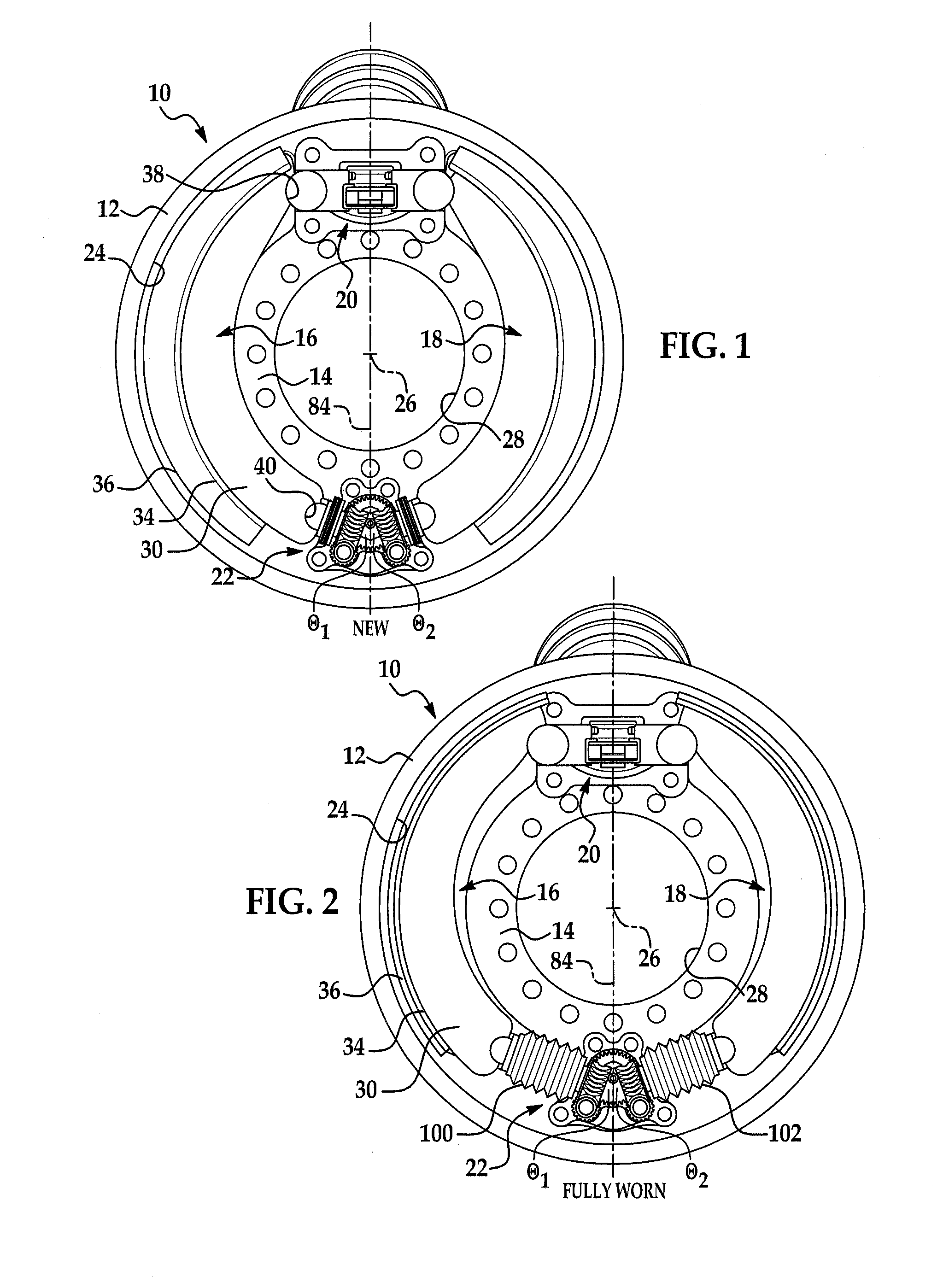
[0014]Referring now to the drawings wherein like reference numerals are used to identify identical components in the various views, FIGS. 1-2 illustrate a brake 10 in accordance with one embodiment of the present invention. Brake 10 is particularly adapted for use in heavy trucks. It should be understood, however, that brake 10 may be used on a wide variety of vehicles and in non-vehicular applications. Brake 10 may include a brake drum 12, a brake spider 14, brake shoes 16, 18, an actuator 20, and an anchor assembly 22 in accordance with the present invention.

[0015]Brake drum 12 provides a braking surface 24 and is conventional in the art. Drum 12 may be made from conventional metals and metal alloys such as steel or cast iron. Drum 12 is annular and rotates with the vehicle wheel or wheels at one end of an axle about a central axis 26 extending through the axle (and into and out of drawings in FIGS. 1-2).

[0016]Brake spider 14 is provided to mount the various components of brake 10...


PUM


Abstract

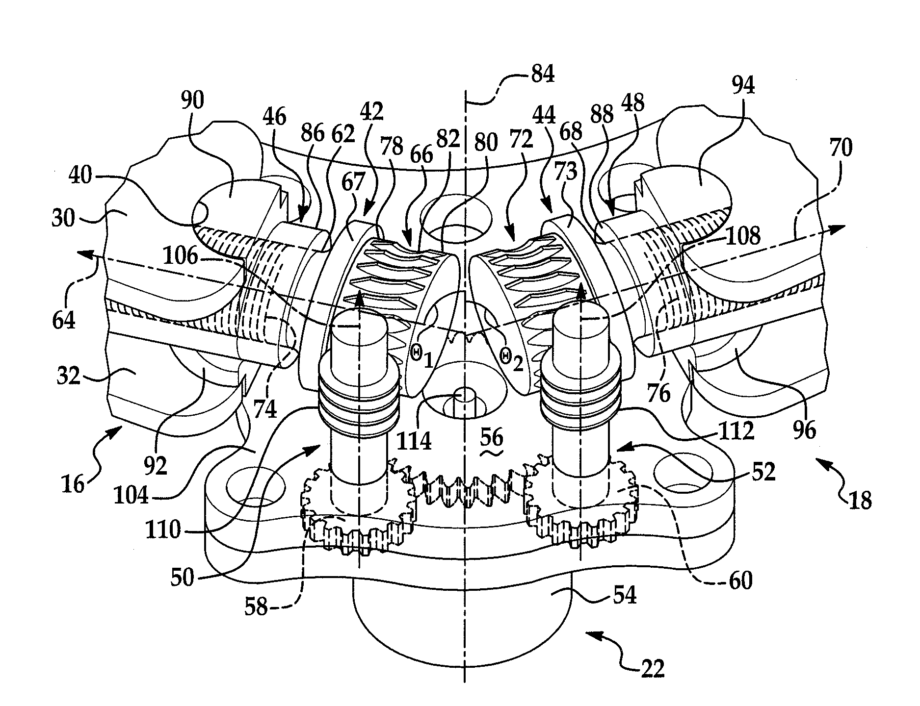
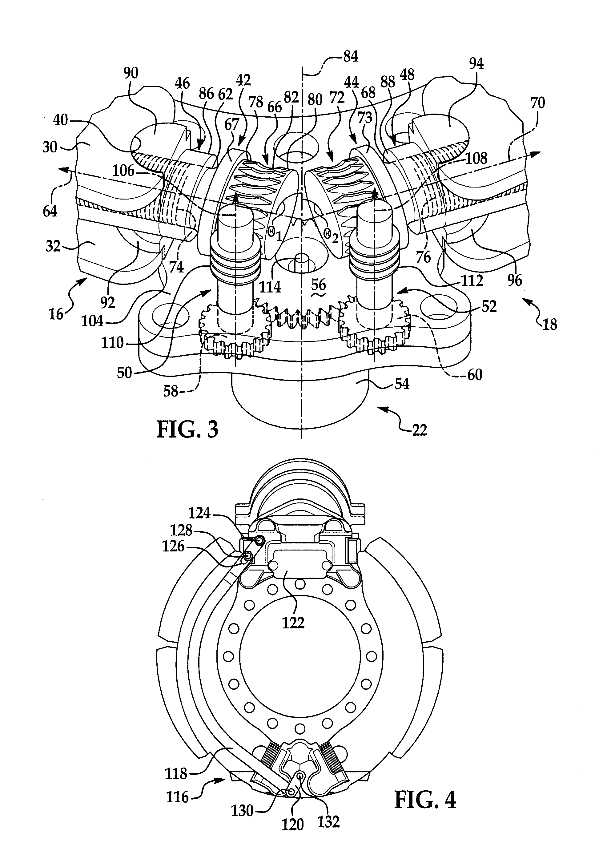
An anchor assembly is provided that permits adjustment of the brake shoes in a drum brake to account for wear. The assembly includes first and second adjuster shafts each having a plurality of threads and first and second pilot connectors. The pilot connectors each have a plurality of threads in engagement with the threads of a corresponding adjuster shaft. The pilot connectors each engage one end of a corresponding brake shoe. Rotation of each adjuster shaft causes longitudinal movement of a corresponding pilot connector in engagement with a corresponding brake shoe along an axis to adjust a position of the brake shoe.

Description

BACKGROUND OF THE INVENTION[0001]1. Field of the Invention[0002]This invention relates to drum brakes and, in particular, to a variable position anchor assembly that permits adjustment of the position of brake shoes relative to the brake drum to account for wear.[0003]2. Discussion of Related Art[0004]A conventional drum brake includes a brake drum that rotates with a wheel or wheels proximate to one end of an axle. The brake drum defines a radially inner braking surface. A brake spider is disposed about the axle and supports an anchor pin that extends from the spider. A pair of brake shoes are pivotally mounted at one end on the anchor. The opposite end of each brake shoe is engaged by an actuator such as a cam or hydraulic piston or wedge to move the brake shoes between positions of engagement and disengagement with the braking surface of the brake drum.[0005]Over time the clearance between the brake shoes and the braking surface of the drum increases with wear of the brake shoe l...

Claims


Application Information

Patent Timeline
Patent Type & Authority Patents(United States)
IPC IPC(8): F16D65/38F16D125/40F16D51/18F16D123/00F16D121/24F16D65/66F16D125/22F16D51/00F16D125/20F16D55/14F16D65/56
CPCF16D51/18F16D2125/20F16D2123/00F16D2125/40F16D65/565F16D2065/386F16D2121/24F16D2125/22F16D65/66
Inventor FLODIN, TROY A.BANKS, DANIEL E.CHAMBERLIN, MICHAEL A.CLARK, JAMES R.RUNELS, THOMAS L.
Owner BENDIKS SPAJSER FAUNDEJSHN BREJK LLK
Learn More