Connector

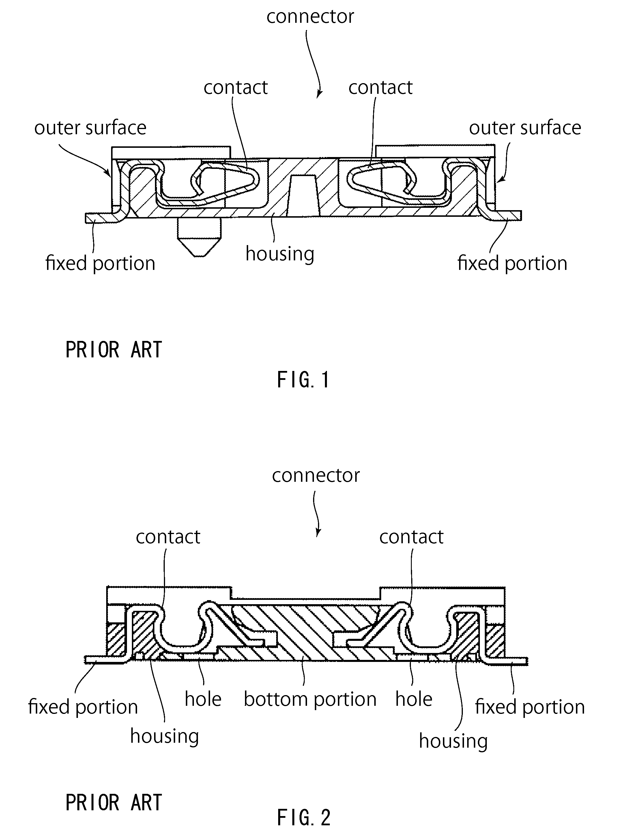
a technology of connecting rods and connectors, applied in the direction of coupling contact members, coupling device details, coupling device connections, etc., can solve the problems of contact therefore being rusted, contact being contaminated, etc., and achieve the effect of less contamination and less exposed

Active Publication Date: 2014-11-18
JAPAN AVIATION ELECTRONICS IND LTD +1
View PDF240 Cites 83 Cited by
  • Summary
  • Abstract
  • Description
  • Claims
  • Application Information

AI Technical Summary

Benefits of technology

[0006]It is therefore an object of the present invention to provide a connector having a contact configured to be less exposed, particularly in a mated state, and less contaminated.

Problems solved by technology

The contact therefore may be rusted.
Moreover, the contact may be contaminated by scattered flux or solder when the connector is attached to a circuit board.

Method used


Image

  • Connector
  • Connector
  • Connector

Examples


Embodiment Construction

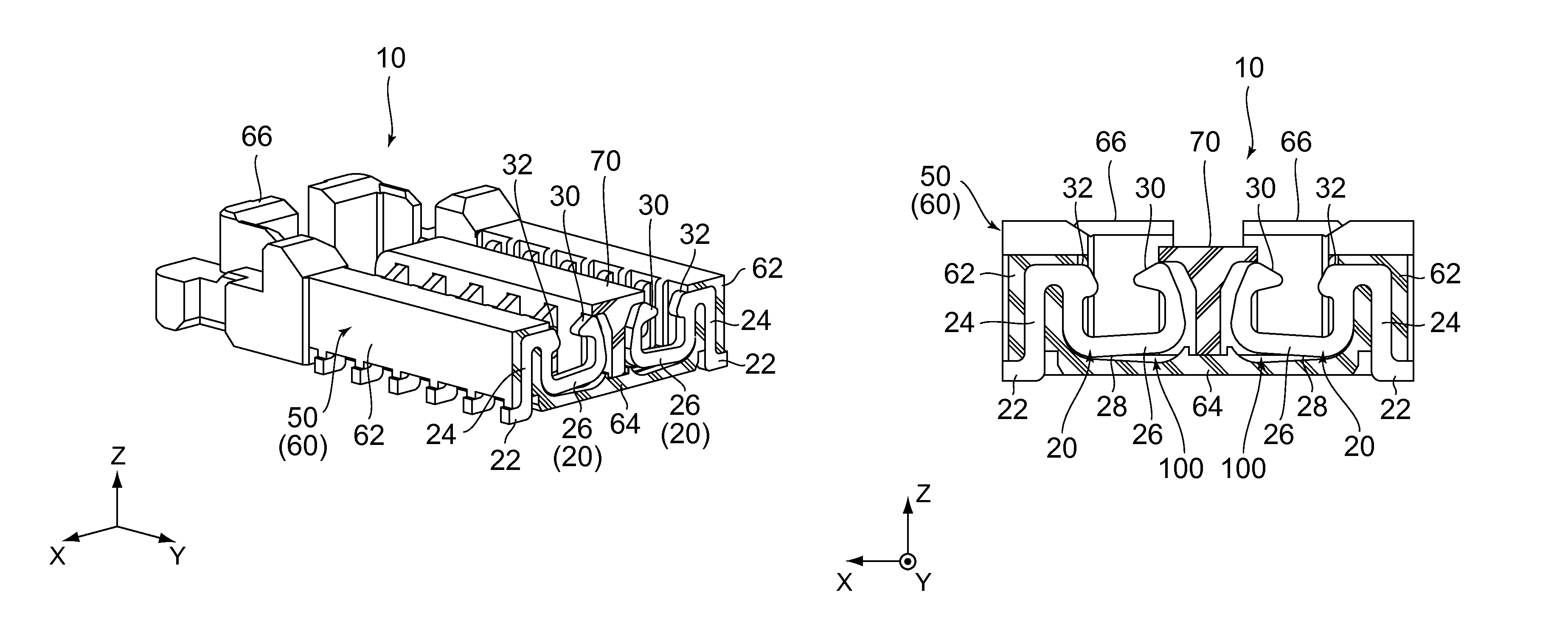
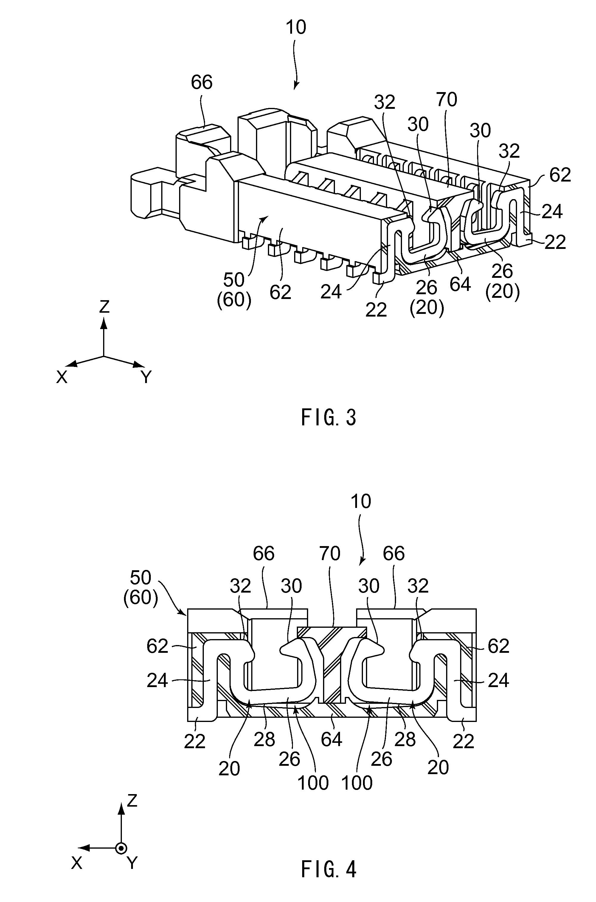
[0019]Referring to FIGS. 3 to 6, a connector 10 according to an embodiment of the present invention is configured to be mounted on a circuit board (not shown) for use.

[0020]The connector 10 comprises a plurality of contacts 20 each made of a conductive material and a housing 50 made of an insulating material. The connector 10 may further comprise a metallic member such as a reinforcement member, a shell or a hold-down.

[0021]As can be seen from FIGS. 3, 5 and 6, the contacts 20 are classified into two groups. The contacts 20 of each of the groups are arranged in the Y-direction (pitch direction). The contacts 20 of one of the two groups are arranged back-to-back with the contacts 20 of another one of the two groups in the X-direction (predetermined direction), respectively. As shown in FIG. 4, the contacts 20 of one of the two groups and the contacts 20 of another one of the two groups are arranged symmetrically relative to the middle of the housing 50 in the X-direction.

[0022]As sho...


PUM


Abstract

A connector has a contact and a housing. The contact has a fixed portion, a contact portion, a spring portion and a held portion. The spring portion supports the contact portion. The held portion is located between the fixed portion and the spring portion. The housing has a sidewall portion and a bottom portion The sidewall portion is located outward of the spring portion in a predetermined direction and holds the held portion. The bottom portion is located under the spring portion in a vertical direction perpendicular to the predetermined direction. The housing has a gap between a lower surface of the spring portion and the bottom portion. The bottom portion and the sidewall portion hide the contact except the fixed portion both when the connector is seen from below along the vertical direction and when the connector is seen from the outside along the predetermined direction.

Description

BACKGROUND OF THE INVENTION[0001]This invention relates to a connector configured to be mounted on a circuit board.[0002]As shown in FIG. 1, a connector disclosed in JP-A 2004-55463 comprises a housing made of an insulating material and contacts held by the housing. The contacts are press-fit in the housing from above.[0003]As shown in FIG. 2, a connector disclosed in WO 2008 / 139554 comprises a housing made of an insulating material and contacts held by the housing. The housing is formed from two members. Each of the contacts is partially embedded in one of the members of the housing via insert-molding.[0004]As for the connector of JP-A 2004-55463, the housing is required to have an outer surface formed with a region where a fixed portion of the contact passes through when the contact is press-fit into the housing. Accordingly, the contact is visible when the outer surface of the housing is seen from the outside. Thus, the contact may be exposed to moisture or gases through the oute...

Claims


Application Information

Patent Timeline
Patent Type & Authority Patents(United States)
IPC IPC(8): H01R12/70H01R12/00
CPCH01R13/20H01R12/73H01R12/716H01R12/7082H01R43/24H01R13/405H01R12/71H01R13/52H01R13/631
Inventor NISHIMURA, TAKAYUKIMOTOJIMA, JOE
Owner JAPAN AVIATION ELECTRONICS IND LTD
Why Eureka
Try Eureka