Tank arrangement adapted for a submersible pump

a technology of submersible pumps and tanks, applied in the direction of floating buildings, self-bailing equipment/scuppers, vessel safety, etc., can solve the problems of unfavorable unfavorable air discharge, and inability to avoid air in the pump assembly, etc., to achieve simple yet effective air discharge, easy replacement, removal or servi

Active Publication Date: 2011-06-02
GVA CONSULTANTS
View PDF15 Cites 3 Cited by
  • Summary
  • Abstract
  • Description
  • Claims
  • Application Information

AI Technical Summary

Benefits of technology

[0018]The caisson can be arranged to extend a distance D at least past the at least one tank wall, and away from the storage space of the tank arrangement. The distance D is about the range of 0.1-50 meters. For a short caisson the distance D is about 0.1-8 meters, preferably about 0.1-5 meters, more preferably about 0.2-2, even more preferably 0.2-1 meters. This permits a tank arrangement to which a submersible pump can be easily replaced, removed or serviced.
[0019]In an embodiment of the present invention, the tank arrangement comprises means for removing air, or excess air, from the storage space. This will prevent air from entering the submersible pump in an undesired manner. It may however permit air to be circulated back to the submersible pump and especially to the low side of the submersible pump. The means for removing the air

Problems solved by technology

However, in some operations, intrusion of air cannot be avoided.
For example, when a ballast tank is drained of water, there is a risk that air, at low tank level in the ballast tank, will be mixed with ballast water and guided towards to, and later introduced into the pumps such that air will be entrained in the water filling assembly and—at a later stage—in at least a portion of the pump assembly.
As such, when a ballast tank is to be emptied of water, there is a risk that the air in the pump assembly will be guided towards the pump and hence introduced in the pump.
Since air generally adversely affects a pump, the presence of air is undesired.
Since a pump generally has an optimum operating condition at a s

Method used


Image

  • Tank arrangement adapted for a submersible pump
  • Tank arrangement adapted for a submersible pump
  • Tank arrangement adapted for a submersible pump

Examples


second embodiment

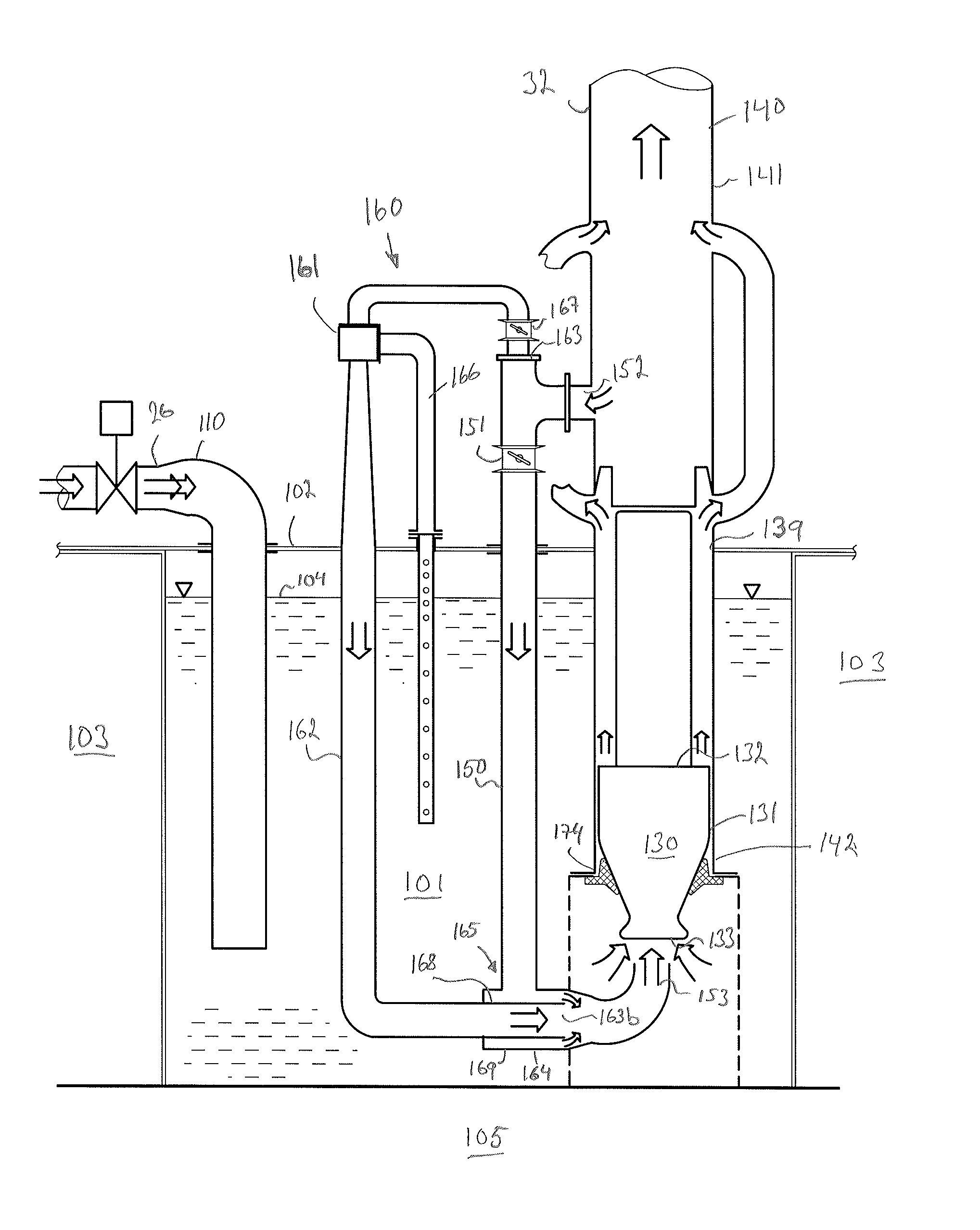
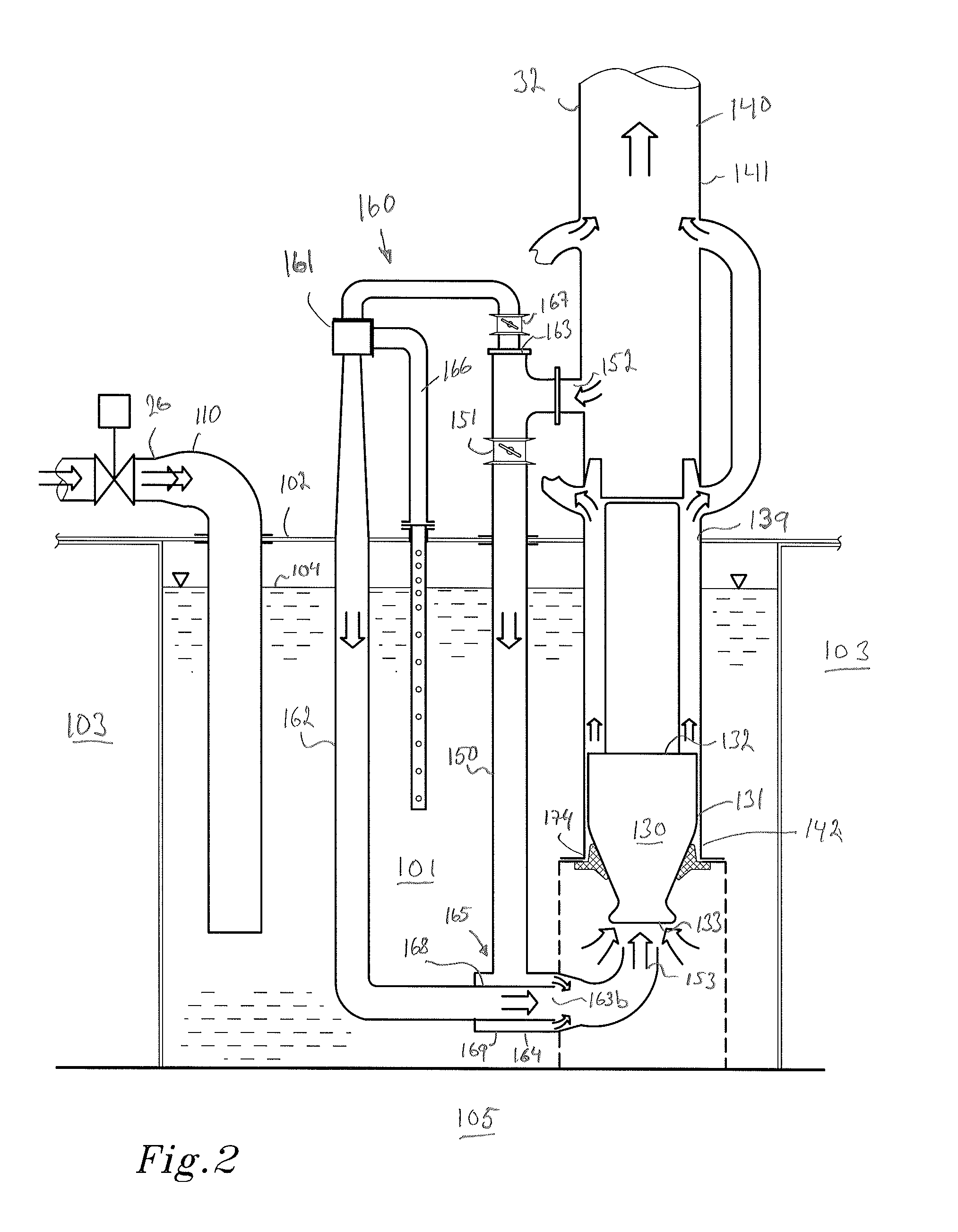
[0052]FIG. 3 shows a tank arrangement 100 according to the present invention. Similar features will be referred to with similar reference numbers. As is noticed, the opening adapted to receive the submersible pump 130 is not more than a recess 170 having a circular collar 171. The circular collar 171 is adapted to enable a seal between a reclosable lid 172 or optionally parts of the submersible pump 130. The reclosable lid 172 is resting on the circular collar 171.

[0053]The reclosable lid 172 enables an operator of a derrick 173 to remove or insert a submersible pump 130 through the outlet 139, into the recess 170 and thereby also into the storage space 101. A short caisson 140, as shown in FIG. 3, enables an operator to move the submersible pump 130 to an alternative or a second tank arrangement similar or different to the tank arrangement 100, according to the present invention, to a service station (not shown), or the like.

[0054]A water conduit 145 is arranged to the collar 171 o...

third embodiment

[0055]FIG. 4 shows a tank arrangement 100 according to the present invention. The tank arrangement 100 comprises as mentioned with reference to FIGS. 2 and 3, a storage space 101, at least one tank wall 102, at least one inlet for introducing bilge water, emergency bilge water or ballast water, a recess 170 for receiving a submersible pump 130 at a submersible pump position 131 and a reclosable lid 172.

[0056]The reclosable lid 172 is adapted to permit power and / or control cables 176 to the submersible pump 130 to extend there through or optionally via a cable connection on each side of the reclosable lid 172. The power and / or control cable 176 can however extend through any other wall of the tank arrangement 100. As is noticed in FIG. 4, the power and / or control cable 176 has a designated length, indicated by that the power and / or control cable 176 is illustrated in a serpentine like manner. By having a designated length of the power and / or control cable 176, the submersible pump 13...


PUM


Abstract

The present invention relates to a ballast system for a marine structure. The ballast system comprises a ballast tank which is in fluid communication with a tank arrangement for temporarily holding bilge fluid and/or ballast fluid in a marine structure. The tank arrangement comprises a storage space defined by at least one tank wall, at least one fluid inlet for introducing the bilge fluid and/or ballast fluid in the storage space, and at least one fluid outlet permitting removal of at least parts of the bilge fluid and/or ballast fluid from the storage space. The at least one fluid outlet is at least partly formed by a caisson adapted for receiving a submersible pump at a submersible pump position in the storage space.

Description

CROSS-REFERENCE TO RELATED APPLICATIONS[0001]This application claims benefit of U.S. Provisional Patent Application No. 61 / 179,416, filed on May 19, 2009 and of Swedish Patent Application 0950358-2 filed on May 19, 2009.BACKGROUND[0002]1. Field[0003]The present invention relates to a tank arrangement for a marine structure. The tank arrangement is adapted for a submersible pump, the tank arrangement comprises a circulation conduit for circulating liquid to enable the submersible pump to operate in an advantageous condition substantially at all time. The present invention also relates to an assembly of a submersible pump and a tank arrangement.[0004]2. Background of the Invention[0005]A marine structure, such as a ship or a semi-submersible unit, is often provided with one or more ballast systems in order to control the draught and / or the inclination of the marine structure. Generally, a ballast system comprises a ballast tank, and in fact often a plurality of tanks, which is adapted...

Claims


Application Information

Patent Timeline
IPC IPC(8): B63B39/03B63B43/06B63B13/00
CPCB63B13/00B63B27/24F04D13/08F04D15/0022
Inventor LIBERG, LARS-OLOF
Owner GVA CONSULTANTS
Why Eureka
Try Eureka