
Disconnector for switchgear

a technology of disconnector and switch gear, which is applied in the direction of contact mechanism, air-break switch, contact engagement, etc., can solve the problems of difficult to meet the present-day implementation of disconnector, the characteristic of disconnector is prescribed, etc., and achieves simple and cost-effective construction and reliable operation.

Inactive Publication Date: 2014-11-18
EATON IND NETHERLANDS
View PDF5 Cites 3 Cited by
  • Summary
  • Abstract
  • Description
  • Claims
  • Application Information

AI Technical Summary

Benefits of technology

The disconnector in this patent aims to be more reliable and operate better throughout its lifespan, while also being simple and inexpensive to build.

Problems solved by technology

However, the vulnerability of such contact terminals has resulted in prescribed characteristics of the disconnector.
These requirements are hard to meet using present day disconnector implementations.

Method used


Image

  • Disconnector for switchgear
  • Disconnector for switchgear
  • Disconnector for switchgear

Examples


Embodiment Construction

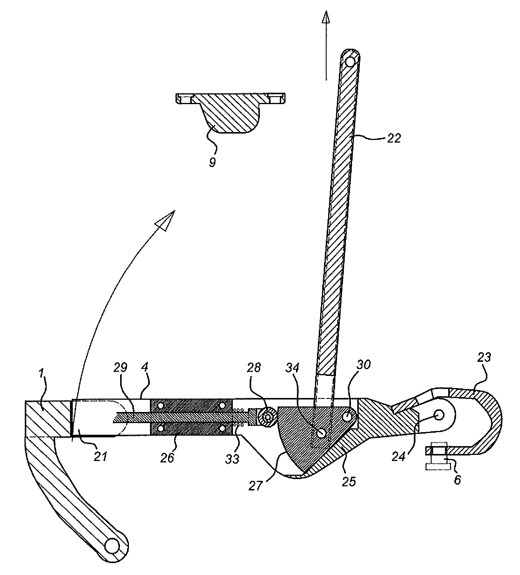
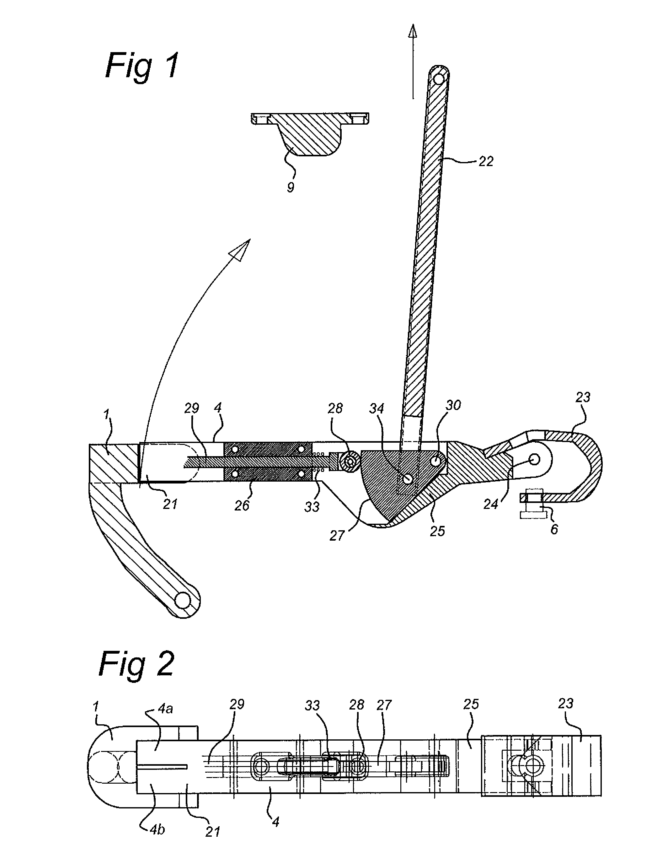
[0021]In FIG. 1, a first embodiment of a disconnector for a switchgear is shown schematically, partly in cross sectional view. The disconnector is arranged to provide an electrical connection between a main terminal 6 (connected to the connector body 4 using a Litze connection 23) and either a first terminal 1 (connected to e.g. a rail of the switchgear system) or a second terminal 9 (connected e.g. to ground, i.e. earth potential). The disconnector is moved in a first direction between a first position (connecting main terminal 6 to first terminal 1) and a second position (connecting main terminal 6 to second terminal 9) by a drive rod 22 connected to connector body 4 (providing a first operating mechanism). In the embodiment shown in FIG. 1 the first direction is a tangential direction around a fixed journal point 24.

[0022]In the embodiment shown in FIG. 1, the connector body 4 moves in a swaying manner around fixed journal point 24 from the first to second position and back. Acco...


PUM


Abstract

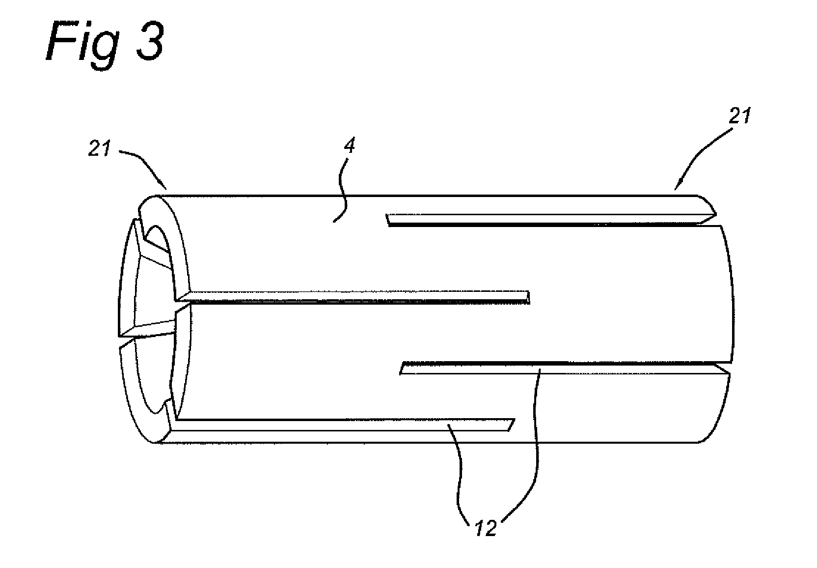
Disconnector for switchgear, having a first contact position, in which a contact is between main and first terminals, and a second contact position, in which a contact is between the main and second terminal. The disconnector includes a connector body moveable in a first direction between the first and second positions and having an end extendable in a direction substantially perpendicular to the first direction for providing a contact force between the end and the first, second or main terminals, a first operating mechanism arranged to move the body between the first and second positions, and a second operating mechanism arranged to extend the end when the disconnector is in either the first or second contact positions, in which the end includes a conical inside surface and the second operating mechanism includes a first shaft having a first conically shaped end positioned inside the conical inside surface.

Description

FIELD OF THE INVENTION[0001]The present invention relates to a disconnector for a switch gear system having a first contact position, in which an electrical contact is provided between a main terminal and a first terminal (e.g. a rail or bus of the switchgear), and a second contact position, in which an electrical contact is provided between the main terminal and a second terminal (e.g. a ground terminal of the switchgear).PRIOR ART[0002]Such a disconnector is well known in present day medium voltage switchgears, usually in the form of an embodiment having sliding contacts. As the disconnector is normally operated in a switched off system (i.e. not having to switch electrical currents), it is possible to use relatively low cost and simple contact terminals. However, the vulnerability of such contact terminals has resulted in prescribed characteristics of the disconnector. The contact resistance has to remain within certain boundaries (e.g. 10%), also after a durability test of for e...

Claims


Application Information

Patent Timeline
Patent Type & Authority Patents(United States)
IPC IPC(8): H01H31/24H01H1/42H01H3/46H01H15/00H01H13/00H01H31/32H01H1/38
CPCH01H1/38H01H31/32H01H1/42H01H3/46H01H31/24H01H3/00H01H2221/08H01H3/38
Inventor NITERT, GERHARDUS LEONARDUSLAMMERS, AREND JAN WILLEM
Owner EATON IND NETHERLANDS
Learn More