Detecting the location of an object on a touch surface
What is Al technical title?
Al technical title is built by PatSnap Al team. It summarizes the technical point description of the patent document.
a technology of touch surface and object, which is applied in the direction of instruments, static indicating devices, optical elements, etc., can solve the problems of increasing the energy consumption not readily scalable, and the cost of known ftir techniques, so as to achieve the effect of increasing and reducing the cost of illuminating the panel
Inactive Publication Date: 2014-11-18
FLATFROG LAB
View PDF62 Cites 34 Cited by
Summary
Abstract
Description
Claims
Application Information
AI Technical Summary
This helps you quickly interpret patents by identifying the three key elements:
Problems solved by technology
Method used
Benefits of technology
Problems solved by technology
These known FTIR techniques suffer from being costly, i.a. since they require the use of a large number of detectors, and possibly a large number of light sources.
Furthermore, they are not readily scalable since the required number of detectors / sources increases significantly with the surface area of the panel.
Still further, the energy consumption for illuminating the panel may be considerable and increases significantly with increasing surface area of the panel.
Method used
Image
Click on the blue label to locate the original text in one second.
Reading with bidirectional positioning of images and text.
Examples
Embodiment Construction
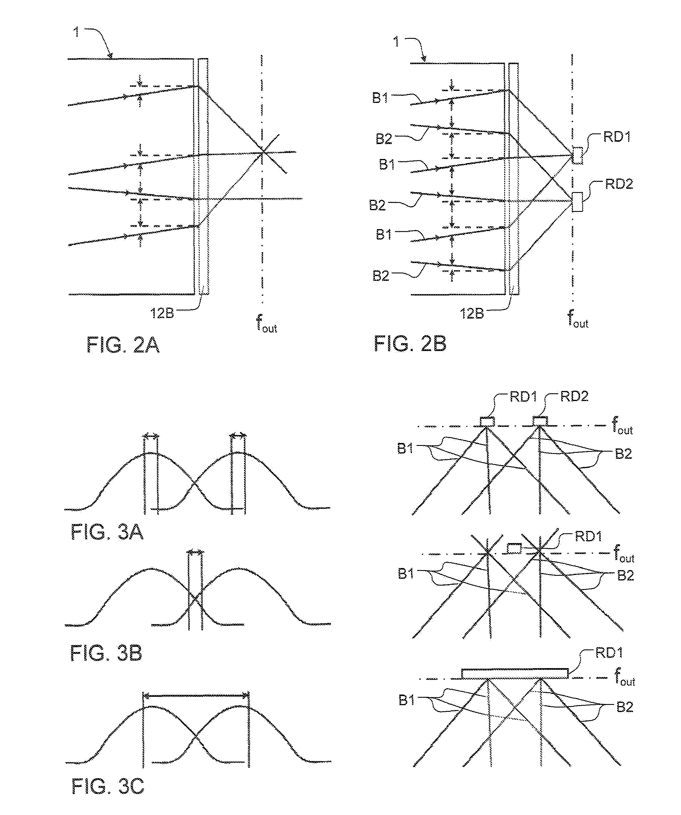
[0050]The following description starts by describing an embodiment of an overall touch-sensing system according to the present invention, followed by different embodiments of a detection arrangement for such a system. Thereafter, exemplifying implementation details relevant to the overall system are given, and aspects of multi-touch detection are discussed. Subsequently, different beam sweeps and mutual arrangements of beams during these sweeps are discussed in detail, and a description is given of different embodiments of an illumination arrangement for generating the beam sweeps. Finally, an exemplifying algorithm for determining touch locations in the system is given. Throughout the description, the same reference numerals are used to identify corresponding elements.
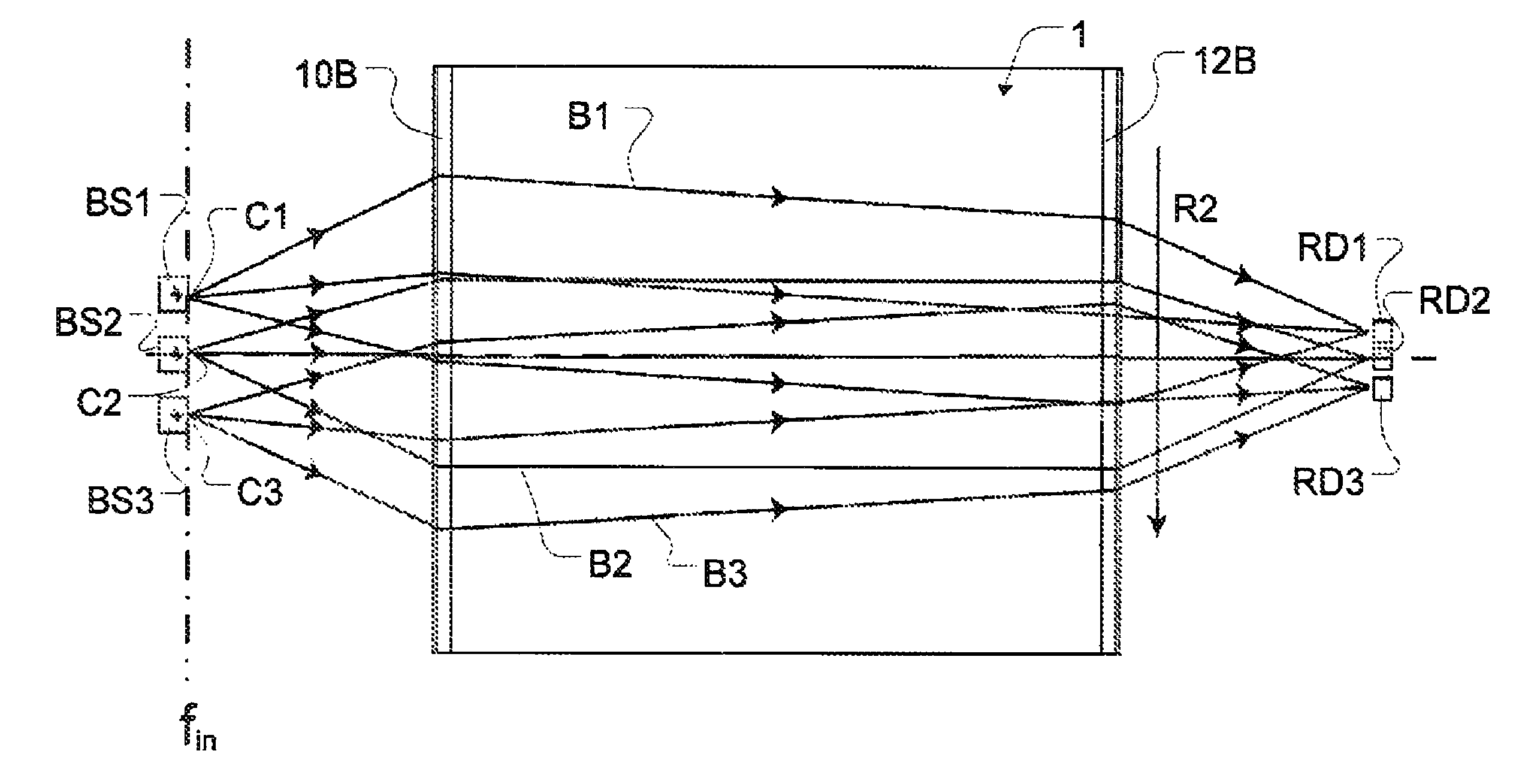
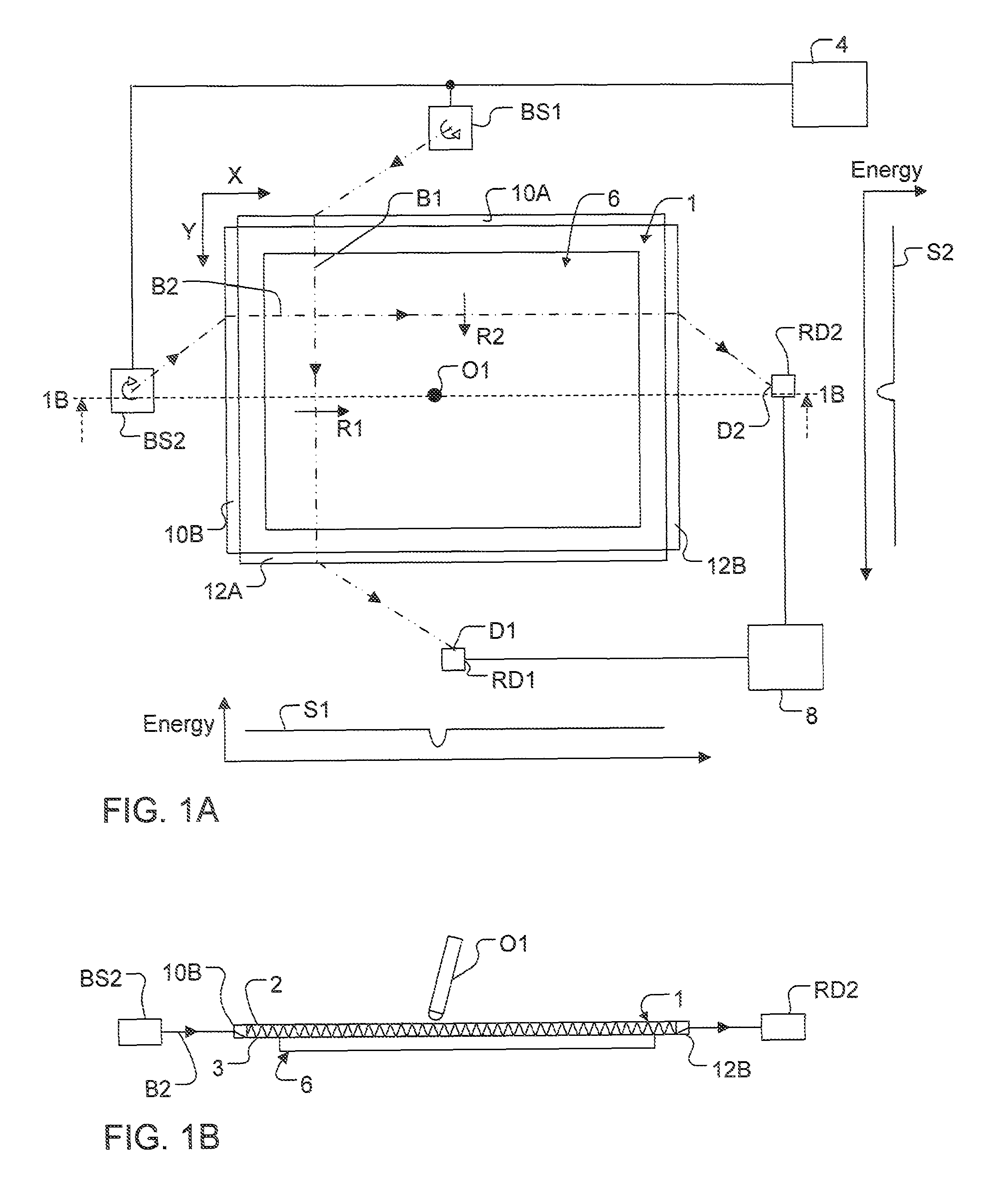
[0051]The present invention relates to a technique for determining the location of an object that touches a surface of a radiation transmissive panel. An example of a touch-sensing system including such a panel 1 is s...
PUM
Abstract
An apparatus is operated to determine the location of at least one object on a touch surface of a light transmissive panel. In the apparatus, an illumination arrangement introduces radiation into the panel for propagation by internal reflection between the touch surface and the opposite surface, so as to generate a grid of intersecting radiation paths in a sensing area, and a detection arrangement measures the transmitted energy in the radiation paths. A data processor then determines, based on the transmitted energy, the location based on an attenuation of two or more radiation paths caused by the object touching the touch surface within the sensing area. In the apparatus, the illumination arrangement generates at least a subset of the radiation paths by sweeping at least one beam of radiation along the touch surface. The detection arrangement comprises a fixed re-directing device which receives and re-directs the beam onto a common detection point while the beam is swept along the touch surface, and a radiation detector which is located at the common detection point to measure the energy of the beam(s).
Description
CROSS-REFERENCE TO RELATED APPLICATIONS[0001]The present application claims the benefit of Swedish patent application No. 0801466-4, filed on Jun. 23, 2008, U.S. provisional application No. 61 / 129,373, filed on Jun. 23, 2008, Swedish patent application No. 0801467-2, filed on Jun. 23, 2008, U.S. provisional application No. 61 / 129,372, filed on Jun. 23, 2008, Swedish patent application No. 0950245-1, filed on Apr. 15, 2009, and U.S. provisional application No. 61 / 202,875, filed on Apr. 15, 2009, all of which are incorporated herein by reference.TECHNICAL FIELD[0002]The present invention relates to techniques for detecting the location of an object on a touch surface. The touch surface may be part of a touch-sensitive panel.BACKGROUND ART[0003]To an increasing extent, touch-sensitive panels are being used for providing input data to computers, electronic measurement and test equipment, gaming devices, etc. The panel may be provided with a graphical user interface (GUI) for a user to i...
Claims
Application Information
Patent Timeline
Application Date:The date an application was filed.
Publication Date:The date a patent or application was officially published.
First Publication Date:The earliest publication date of a patent with the same application number.
Issue Date:Publication date of the patent grant document.
PCT Entry Date:The Entry date of PCT National Phase.
Estimated Expiry Date:The statutory expiry date of a patent right according to the Patent Law, and it is the longest term of protection that the patent right can achieve without the termination of the patent right due to other reasons(Term extension factor has been taken into account ).
Invalid Date:Actual expiry date is based on effective date or publication date of legal transaction data of invalid patent.