System for wavefront analysis and optical system having a microscope and a system for wavefront analysis

a wavefront analysis and optical system technology, applied in the field of optical systems and systems for wavefront analysis, can solve the problems of insufficient wavefront analysis of common microscopes, and achieve the effect of high dynamic rang

Active Publication Date: 2014-11-18
CARL ZEISS MEDITEC AG
View PDF18 Cites 3 Cited by
  • Summary
  • Abstract
  • Description
  • Claims
  • Application Information

AI Technical Summary

Benefits of technology

[0008]The housing of the microscope and / or the housing of the assembly may be designed as a rack, case, frame or a combination of these. They may be designed integrally. Alternatively, the housing of the microscope and / or the housing of the assembly consist of a plurality of parts, which are mounted together, for example by using detachable or non-detachable fixing devices, such as screws, rivets, welding seams or the like. The microscope housing and the housing of the assembly serve to provide a basic structure at which further components such as lenses or mirrors may be supported.
[0071]By adjusting the optical path of the wavefront beam path between the second lens group and the third lens group, wavefront measuring light, which emanates from the object region, and which has spherical wavefronts, may be converted into measuring light having substantially plane wavefronts. Hence, by an adjusting the optical path between the second lens group and the third lens group, a compensation of the shape of the wavefront may be performed. Thereby, it is possible for example to examine eyes, which are strongly ametropic, without having to use a wavefront sensor with a high dynamic range.

Problems solved by technology

It has shown, that commonly used microscopes are insufficient for performing wavefront analysis.

Method used


Image

  • System for wavefront analysis and optical system having a microscope and a system for wavefront analysis
  • System for wavefront analysis and optical system having a microscope and a system for wavefront analysis
  • System for wavefront analysis and optical system having a microscope and a system for wavefront analysis

Examples


Embodiment Construction

[0084]In the exemplary embodiments described below, components that are alike in function and structure are designated as far as possible by alike reference numerals. Therefore, to understand the features of the individual components of a specific embodiment, the descriptions of other embodiments and of the summary of the invention should be referred to.

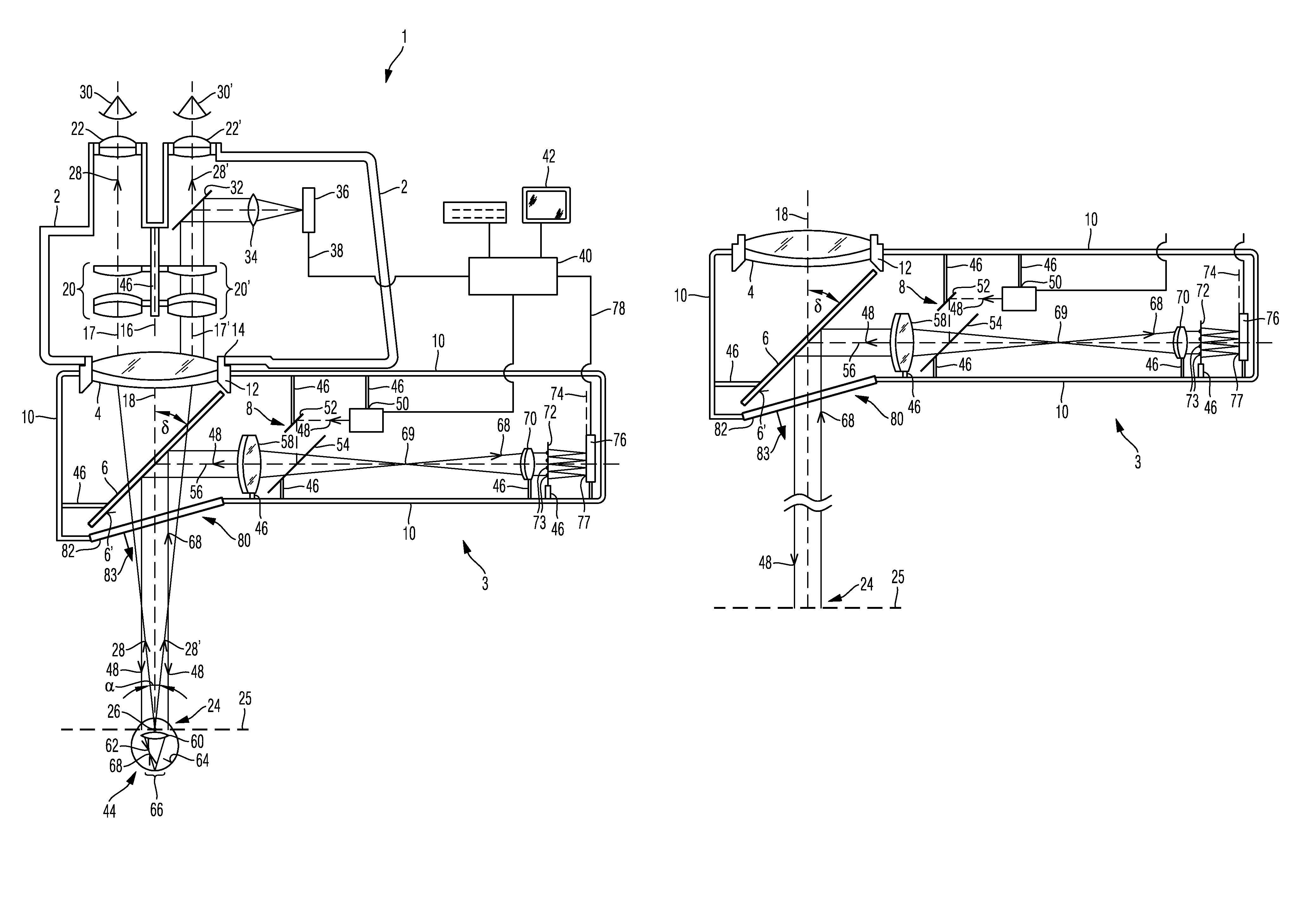
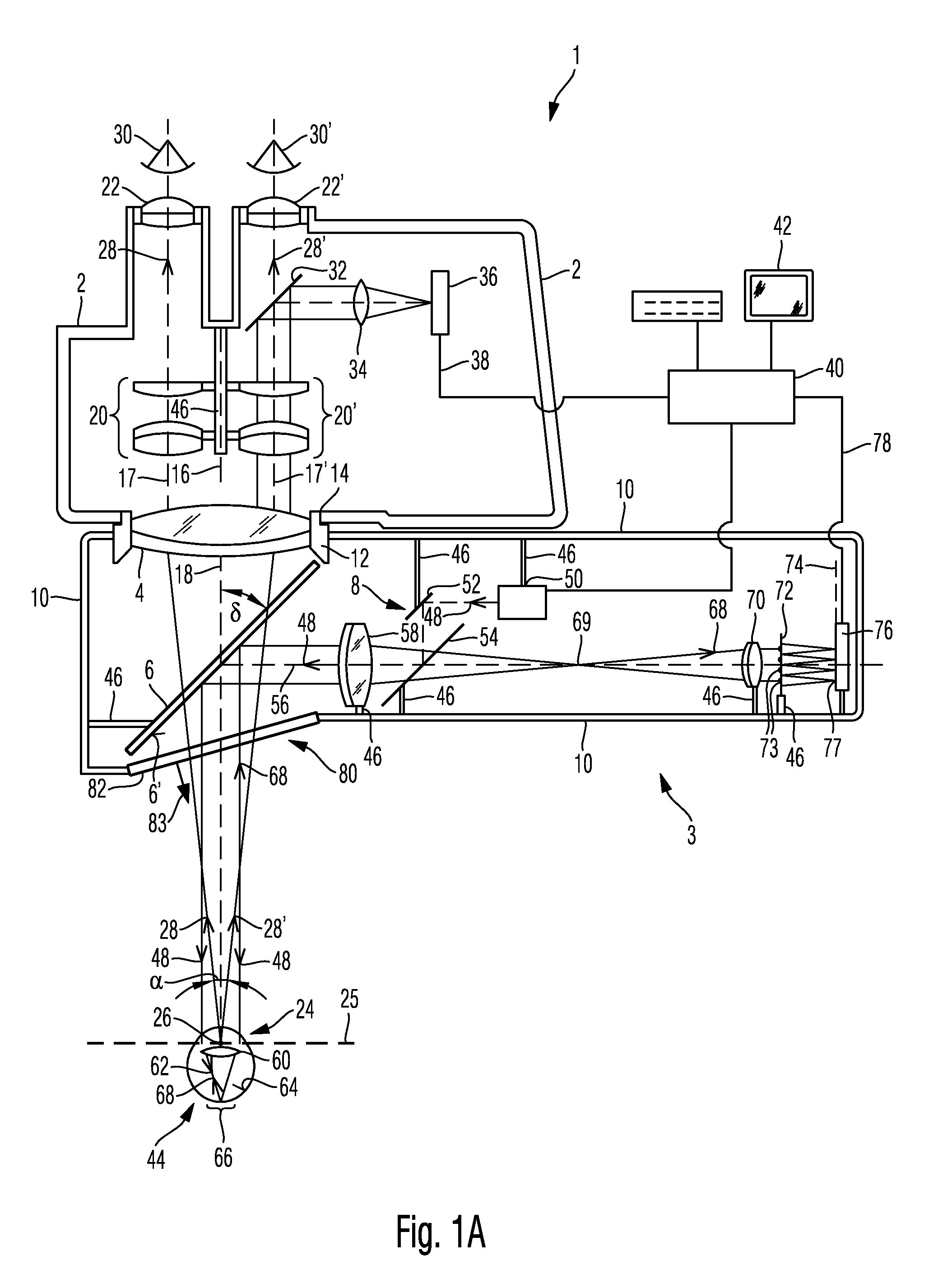
[0085]FIG. 1A shows in a schematic representation an optical system 1 according to an embodiment. The optical system 1 comprises a microscope housing 2, in which a plurality of optical components are arranged, and an assembly 3 for wave front analysis, which comprises an objective lens 4, a dichroic beam splitter 6 and a wave front analysis system 8 as well as an assembly housing 10, which supports these elements. A smallest angle d which is formed between a reflecting face 6′ of the beam splitter 6 and an optical axis 18 of the objective lens 4 amounts to about 45°±5°, in particular 55° and in other embodiments 55°±5°.

[0086]FIG. 1A ...


PUM


Abstract

An optical system, comprising a microscope housing having a coupling opening for a detachable coupling of an objective lens of the optical system such that the objective lens is arranged in a microscope beam path of the optical system for imaging an object region of the objective lens. The optical system further comprises an assembly. The assembly comprises an assembly housing having a coupling element for the detachable coupling of the coupling element and the coupling opening of the microscope housing; a wavefront analysis system, which provides a wavefront beam path; and a beam splitter, which is arranged in the wavefront beam path. The objective lens, the beam splitter and the wavefront analysis system are arranged such that during the coupling of the coupling opening and the coupling element, the objective lens is arranged in the microscope beam path and the object region is arranged in the wavefront beam path.

Description

CROSS-REFERENCES TO RELATED APPLICATIONS[0001]The present application claims priority to and is a continuation of International Patent Application PCT / EP2010 / 005073, which claims priority to DE Patent Application No. 10 2009 037 841.3, filed Aug. 18, 2009 in Germany, entitled “SYSTEM FOR WAVEFRONT ANALYSIS AND OPTICAL SYSTEM HAVING A MICROSCOPE AND A SYSTEM FOR WAVEFRONT ANALYSIS” and to U.S. Provisional Patent Application No. 61 / 234,816, filed Aug. 18, 2009, entitled “SYSTEM FOR WAVEFRONT ANALYSIS AND OPTICAL SYSTEM HAVING A MICROSCOPE AND A SYSTEM FOR WAVEFRONT ANALYSIS”. The present application is related to U.S. patent application Ser. No. 12 / 644,746 filed on Dec. 22, 2009, now U.S. Pat. No. 7,845,798 issued on Dec. 7, 2010. The contents of these applications are hereby incorporated by reference.FIELD OF THE INVENTION[0002]The present invention relates to a system for wavefront analysis and to an optical system comprising a microscope and a system for wavefront analysis. In part...

Claims


Application Information

Patent Timeline
Patent Type & Authority Patents(United States)
IPC IPC(8): G01J9/00G02B21/24A61B3/13G02B21/00G02B21/06G02B21/22
CPCG02B21/24A61B3/13G01J9/00G02B21/00G02B21/22
Inventor KUEBLER, CHRISTOPHKOLSTER, DANIEL
Owner CARL ZEISS MEDITEC AG
Why Eureka
Try Eureka