Reducing agent supply apparatus, method for controlling the same, and exhaust gas purification apparatus

a technology of reducing agent and supply apparatus, which is applied in the direction of mechanical apparatus, engine components, machines/engines, etc., can solve the problems of urea aqueous solution remaining in the small gap, the urea aqueous solution remaining in the reducing agent injection valve is more likely to be heated, and the cooling means also stops working, so as to achieve the effect of increasing the purification efficiency of nox

Active Publication Date: 2014-11-25
BOSCH CORP
View PDF11 Cites 9 Cited by
  • Summary
  • Abstract
  • Description
  • Claims
  • Application Information

AI Technical Summary

Benefits of technology

[0006]When the remaining urea aqueous solution is heated, the solvent evaporates to increase the concentration, thereby increasing the solidifying point of the urea aqueous solution. Accordingly, in the course of cooling the urea aqueous solution as time elapses, the urea aqueous solution remaining in the reducing agent injection valve becomes more likely to solidify, thereby making the reducing agent injection valve more likely to be stuck closed.
[0038]According to the exhaust gas purification apparatus of an internal combustion engine of the invention, a reducing agent supply apparatus in which a predefined siphon function portion is provided on part of a reducing agent passage is included so that, even when the reducing agent injection valve is stuck closed, reducing agent solidified in the reducing agent injection valve can be caused to quickly melt, allowing early start of the injection control using the reducing agent injection valve. Accordingly, purification efficiency of NOx can be increased from the start of the internal combustion engine.

Problems solved by technology

However, even if the purge process is performed, it is practically difficult to completely collect urea aqueous solution remaining in a small gap, such as the periphery of a valve body of the reducing agent injection valve.
Furthermore, the reducing agent supply apparatus includes a means for cooling the reducing agent injection valve, so the reducing agent injection valve is cooled while the internal combustion engine is operating, but, in many cases, when the internal combustion engine stops, the cooling means also stops functioning, which makes urea aqueous solution remaining in the reducing agent injection valve more likely to be heated due to influence of heat of the exhaust pipe and the like.
Then, the reducing agent injection valve cannot start the injection control of urea aqueous solution, during which the purification of NOx may be insufficient.

Method used


Image

  • Reducing agent supply apparatus, method for controlling the same, and exhaust gas purification apparatus
  • Reducing agent supply apparatus, method for controlling the same, and exhaust gas purification apparatus
  • Reducing agent supply apparatus, method for controlling the same, and exhaust gas purification apparatus

Examples


Embodiment Construction

[0049]Embodiments of a reducing agent supply apparatus, a method for controlling the reducing agent supply apparatus, and an exhaust gas purification apparatus of an internal combustion engine of the invention are specifically described below with reference to the drawings as appropriate. However, the embodiments described below are intended to show only an aspect of the invention and not intended to limit the invention, so may be appropriately modified within the scope of the invention. Note that, through the drawings, like numerals denote like components, and duplicative descriptions will be appropriately omitted.

[0050]1. Exhaust Gas Purification Apparatus

[0051](1) Overall Configuration

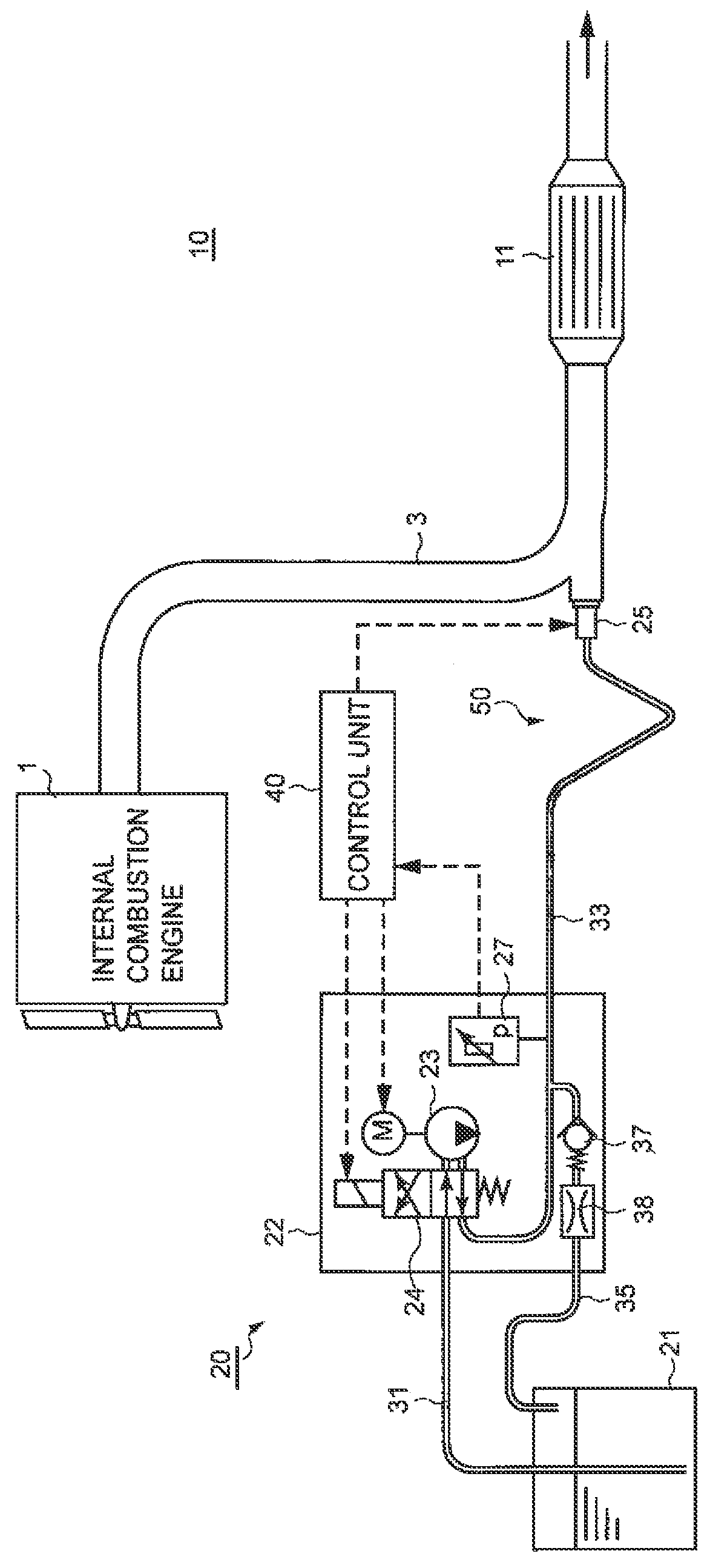
[0052]FIG. 1 shows a configuration example of an exhaust gas purification apparatus 10 in accordance with an embodiment of the invention. This exhaust gas purification apparatus 10 is an exhaust gas purification apparatus that purifies NOx in exhaust gas from an internal combustion engine 1 mounted ...


PUM


Abstract

[Problem] To provide a reducing agent supply apparatus that can quickly melt urea aqueous solution solidified in a reducing agent injection valve to allow early start of the injection control of urea aqueous solution, a method for controlling the reducing agent supply apparatus, and an exhaust gas purification apparatus.[Means for Resolution] A reducing agent supply apparatus, including: a storage tank for storing liquid reducing agent; a pump for pumping the reducing agent; a reducing agent injection valve for injecting the reducing agent pumped by the pump in an exhaust pipe of an internal combustion engine; and a reducing agent passage connecting the pump to the reducing agent injection valve, wherein, when the internal combustion engine stops, a purge process of collecting the reducing agent in the reducing agent passage into the storage tank is performed, and wherein, on part of the reducing agent passage, a siphon function portion is provided for, even when, at the start of the internal combustion engine, the reducing agent injection valve is in injection failure due to solidification of the reducing agent in the reducing agent injection valve, causing some of the reducing agent to reach the reducing agent injection valve after the start of the pump to cause the solidified reducing agent to melt.

Description

BACKGROUND OF THE INVENTION[0001]The present invention relates to a reducing agent supply apparatus for injecting in an exhaust pipe liquid reducing agent used for purifying exhaust gas from an internal combustion engine, a method for controlling the reducing agent supply apparatus, and an exhaust gas purification apparatus.[0002]Conventionally, as one aspect of an exhaust gas purification apparatus for removing nitrogen oxides (NOx) in exhaust gas from an internal combustion engine, a urea selective catalytic reduction (SCR) system is practically used which includes: a reducing agent supply apparatus for injecting urea aqueous solution in an exhaust pipe; and a reducing catalyst that adsorbs ammonia produced by decomposition of urea in urea aqueous solution then selectively reacts NOx in incoming exhaust gas with the ammonia to reduce the NOx.[0003]The reducing agent supply apparatus used in such a urea SCR system includes: a storage tank for storing urea aqueous solution; a pump f...

Claims


Application Information

Patent Timeline
Patent Type & Authority Patents(United States)
IPC IPC(8): F01N3/02F01N3/00F01N3/20F01N3/10
CPCF01N3/2066F01N2900/08F01N2610/02F01N3/208Y02T10/24F01N2610/14F01N2610/1493Y02T10/12
Inventor CHIBA, KUNIHIROKIKUCHI, ATSUSHIMIYAMOTO, TAKESHISAWAKI, TOSHIKIWATANABE, MASANORIWATANABE, HIROYUKI
Owner BOSCH CORP
Why Eureka
Try Eureka