
Stopping device and container comprising such a device

a technology of stopper and container, which is applied in the direction of closure stoppers, caps, and closures using caps, etc., can solve the problems of limiting the access of the stopper, the risk of cutting, and the inability to remove, so as to achieve the effect of simple and intuitive us

Active Publication Date: 2014-11-25
BIOCORP PRODION
View PDF10 Cites 3 Cited by
  • Summary
  • Abstract
  • Description
  • Claims
  • Application Information

AI Technical Summary

Benefits of technology

The invention is a new stopping device that is simple and easy to use. It allows for easy access to the contents of a container by removing the stopper. The device includes a cap that protects the stopper from outside attacks and allows for easy access to the contents of the container. The cap is securely attached to the container using breakable bridges that indicate any interference with the contents. The device also includes a ring that surrounds the neck and stopper, with the stopper protruding above the neck for easy access. The minimum inner diameter of the ring is greater than the maximum diameter of the container's neck. This allows for a reliable and secure attachment of the ring to the container while still allowing for easy access to the stopper.

Problems solved by technology

This may be problematic inasmuch as the metal capsule, which is most often made from aluminum, may break, which requires that it be removed by hand, resulting in a risk of cutting and, most often, the use of the small disassembly tool.
The multi-part structure of this known device makes it expensive.
Furthermore, the capsule limits access to the stopper, which cannot be removed, unless the capsule is destroyed, which is not the normal operation of the device.
The inner diameter of the capsule is equal to that of a rubber stopper intended to be inserted into a neck of the container, which risks causing jamming of the stopper.
Furthermore, the lower part of the capsule must be radially expanded to be immobilized on the neck, which is relatively imprecise and unreliable.

Method used


Image

  • Stopping device and container comprising such a device
  • Stopping device and container comprising such a device
  • Stopping device and container comprising such a device

Examples


Embodiment Construction

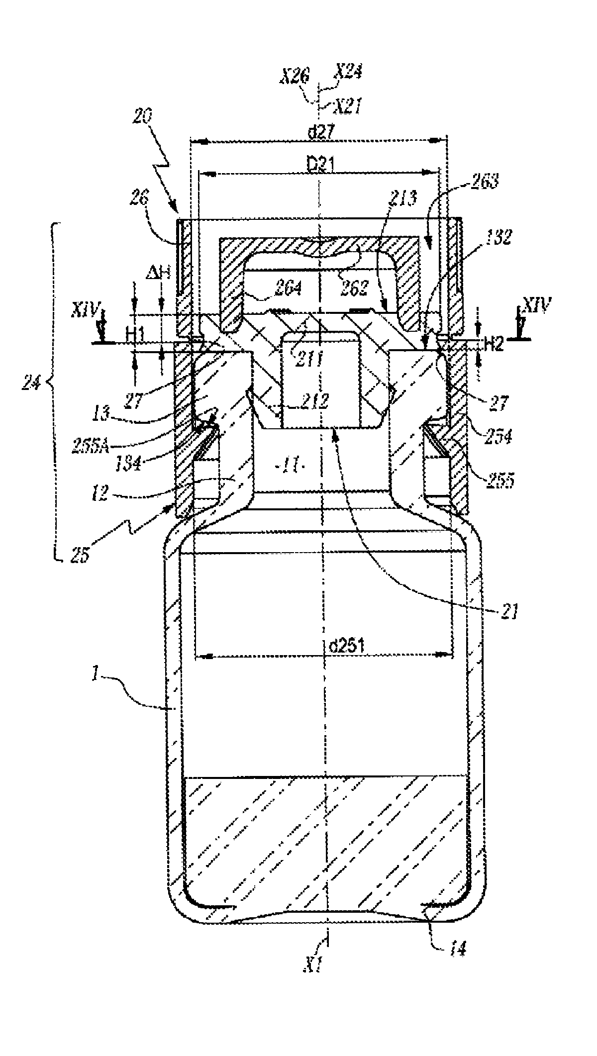
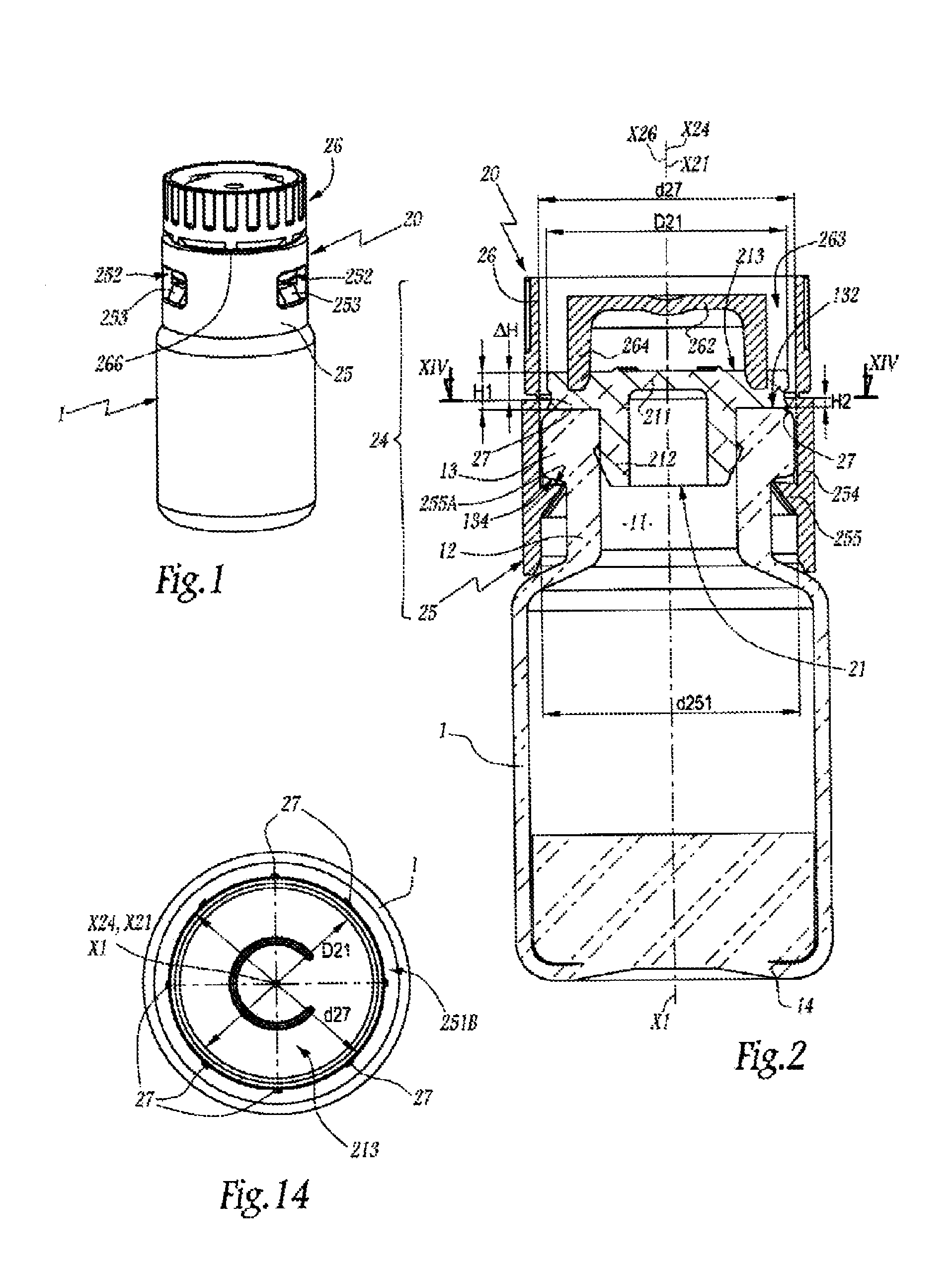
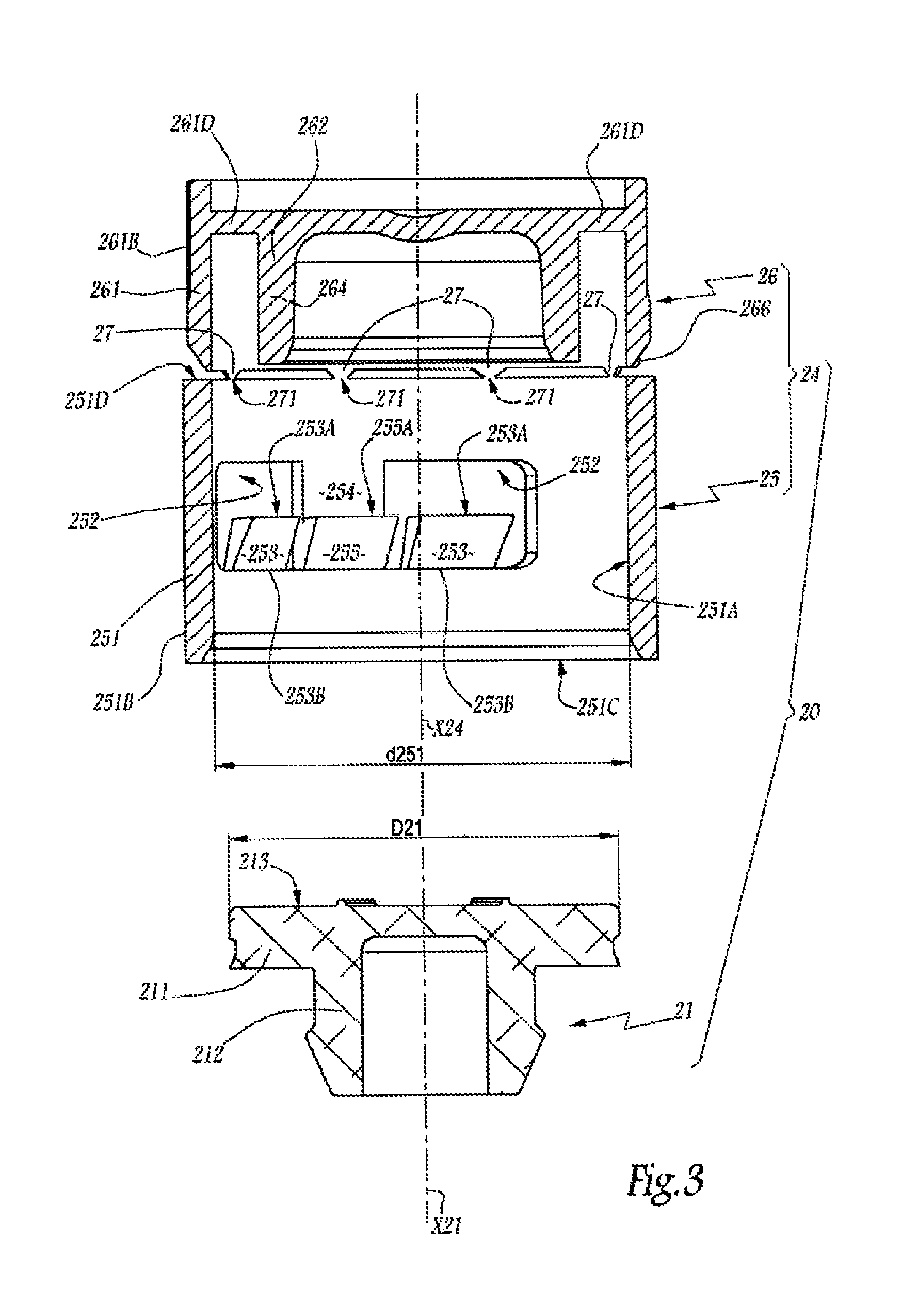
[0031]The bottle 1 shown in the figures is made from glass and comprises a bottleneck 11 defined by a neck 12 having an outer collar 13. X1 denotes the axis of symmetry of the bottle 1, which is also a central axis of the neck 12 and the collar 13. The bottom of the bottle 1 opposite the neck 11 is denoted 14. Reference 132 and 134 denote the surfaces of the collar 13 oriented across from the bottom 14 and toward said bottom, respectively. In other words, the surfaces 132 and 134 respectively make up the lower and upper surfaces of the collar 13 when the bottle 1 rests by its bottom 14 on a horizontal planar surface.

[0032]When the bottle 1 is to be filled, a pipette 200 is inserted therein, through its bottleneck 11, as shown in FIG. 4. When a predetermined quantity of product has been inserted into the bottle 1, the pipette 200 is removed and a stopping device 20 is placed on the neck 12. The device 20 comprises an elastomer stopper 21 with a shape suitable for being partially inse...


PUM


Abstract

A stopping device for a container, comprising a circular stopper for closing the neck of the container, and a cap comprising a synthetic material that covers the neck and the stopper positioned in the neck, the cap comprising a cover and a ring for surrounding the stopper and the neck, the ring having a minimum inner diameter larger than the maximum diameter of the stopper, the ring and the cover being produced as a single component and connected by breakable bridges distributed over a circumference of the ring with an inner diameter that is larger than or equal to the maximum diameter of the stopper, and first locking tabs formed on the inside of the ring facing windows that are radially open towards the outside, and second locking tabs facing a closed part, each second tab formed between two first tabs, facing a strip of material separating windows.

Description

CROSS-REFERENCES TO RELATED APPLICATIONS[0001]This application claims priority benefit under 35 U.S.C. §371 to International Patent Application No. PCT / EP2012 / 060584 entitled STOPPING DEVICE AND CONTAINER COMPRISING SUCH A DEVICE, and filed by inventor Antoine Aneas on Jun. 5, 2012. International Patent Application No. PCT / EP2012 / 060584 claims priority to French Patent Application No. 11 54900, filed by inventor Antoine Aneas on Jun. 6, 2011.FIELD OF THE INVENTION[0002]The invention relates to a stopping device for a container, said device comprising a circular stopper provided to close the neck of the container, as well as a cap. The invention also relates to a container, for example a medicine bottle, equipped with such a stopping device.BACKGROUND OF THE INVENTION[0003]In the field of medicine containers, it is known to use a glass bottle to store an active ingredient in freeze-dried, powdered or liquid solution form. Such a bottle must be closed sealably so as to keep its conten...

Claims


Application Information

Patent Timeline
Patent Type & Authority Patents(United States)
IPC IPC(8): B65D55/10B65D41/58B65D51/24B65D51/18
CPCB65D41/58B65D2101/0023B65D51/241B65D51/18B65D55/10B65D2401/15
Inventor ANEAS, ANTOINE
Owner BIOCORP PRODION
Learn More