Temperature compensated timing signal generator

a timing signal and generator technology, applied in the direction of time pulses, multi-port active networks, electrical equipment, etc., can solve the problems of not being able to add or suppress only a fraction of pulses, adversely affecting the accuracy of the timing signal generator, and not being able to compensate for the timing signal. the temperature compensation method described above is not satisfactory,

Active Publication Date: 2014-11-25
MICRO CRYSTAL
View PDF7 Cites 6 Cited by
  • Summary
  • Abstract
  • Description
  • Claims
  • Application Information

AI Technical Summary

Problems solved by technology

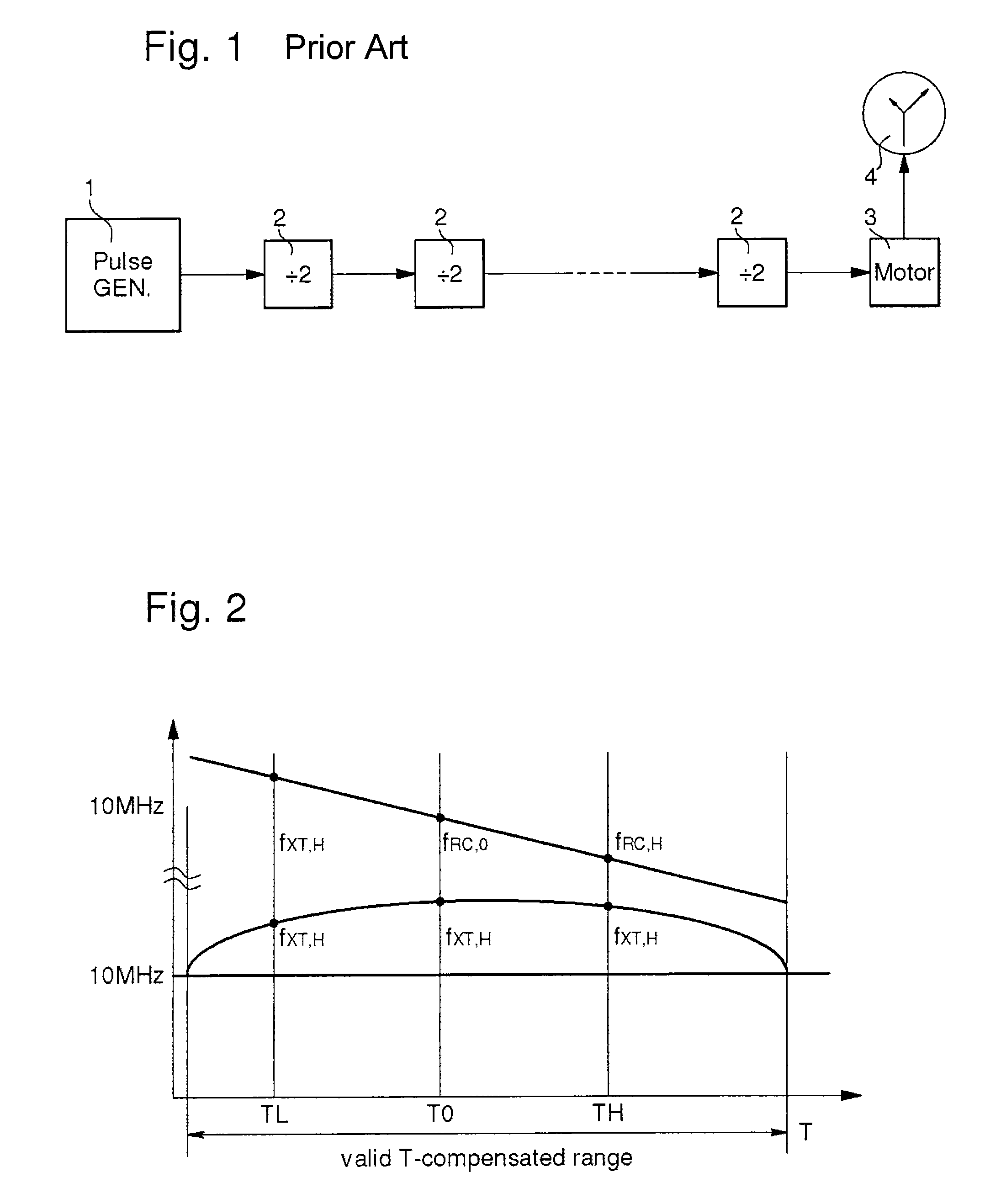
While in principle quartz crystal oscillators are extremely accurate, it is known that their accuracy is detrimentally affected by temperature.
Both inhibition compensation and injection compensation are associated with a quantification error.
The quantification error stems from the fact that it is not possible to add or suppress only a fraction of a pulse.
In this case, the temperature compensation methods described above are not satisfactory.

Method used


Image

  • Temperature compensated timing signal generator
  • Temperature compensated timing signal generator
  • Temperature compensated timing signal generator

Examples


Embodiment Construction

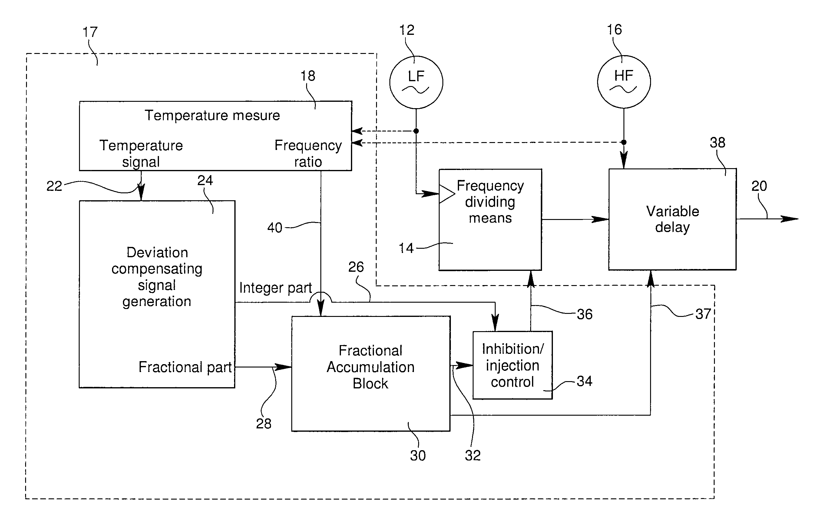
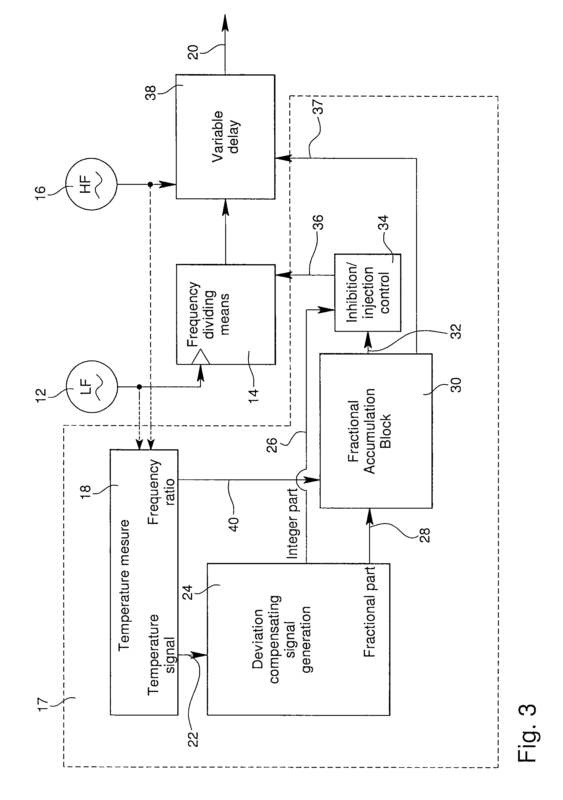
[0016]FIG. 3 is a block diagram illustrating a temperature compensated timing signal generator according to a first embodiment of the present invention. The timing signal generator of FIG. 3 is designed to provide a succession of temperature compensated time unit signal pulses through an output 20. The generator comprises a crystal oscillator 12 arranged to generate a reference time signal. The crystal oscillator can be based for example on a conventional 32.768 kHz quartz crystal tuning-fork resonator. The illustrated generator further comprises a frequency divider 14 arranged to count all the oscillations of the reference time signal, and to output one clock pulse for every 32′768 oscillations of the reference time signal from the crystal oscillator.

[0017]Still referring to FIG. 3, it can be observed that the temperature compensated timing signal generator of the present invention further comprises a high frequency oscillator 16. Oscillator 16 is arranged to provide a clock signal...


PUM


Abstract

The temperature compensated timing signal generator comprises a crystal oscillator that generates a reference time signal, and a divider circuit that receives the reference time signal as input and outputs a coarse time unit signal, the coarse time unit signal having an actual frequency deviating from a desired frequency as a function of temperature of the crystal oscillator. The signal generator also includes a high frequency oscillator that generates an interpolation signal having a frequency greater than the frequency of the crystal oscillator. A finite state machine computes a deviation compensating signal as a function of the temperature signal, the signal comprises an integer part representative of an integer number of pulses to be inhibited or injected in the divider circuit and a fractional part representative of how much the output of a new time unit signal pulse should further be delayed to compensate for any remaining deviation.

Description

FIELD OF THE INVENTION[0001]The present invention relates to temperature compensated timing signal generators. The invention more specifically concerns such timing signal generators in which pulse inhibition and / or pulse injection is used for compensating for variations of the temperature.BACKGROUND OF THE INVENTION[0002]Timing signal generators are known. They comprise an oscillator for providing a timing signal. The oscillator often comprises a quartz crystal resonator used to stabilize the oscillation frequency. While in principle quartz crystal oscillators are extremely accurate, it is known that their accuracy is detrimentally affected by temperature. A quartz crystal basically acts like a mechanical resonator, and any change in the temperature will cause it to expand or contract ever so slightly, thus changing the resonant frequency. In order to overcome the problems of variations in the resonant frequency, several approaches are known from the prior art.[0003]FIG. 1 is a func...

Claims


Application Information

Patent Timeline
Patent Type & Authority Patents(United States)
IPC IPC(8): G04G3/02G04G3/04
CPCG04G3/022G04G3/04
Inventor RUFFIEUX, DAVIDSCOLARI, NICOLA
Owner MICRO CRYSTAL
Why Eureka
Try Eureka