Optical touch apparatus

a touch and optical technology, applied in the field of optical touch, can solve the problems of increasing the cost and affecting the beauty of space design, and achieve the effects of effectively enlarge the imaging region, improve the conventional complicated process of aligning the sensing module accurately, and effectively receiving light signals

Inactive Publication Date: 2014-11-25
RAYDIUM SEMICON
View PDF8 Cites 0 Cited by
  • Summary
  • Abstract
  • Description
  • Claims
  • Application Information

AI Technical Summary

Benefits of technology

[0010]A scope of the invention is to provide an optical touch apparatus having suitable design of optical lens to make the light sensing module capable of receiving light signals effectively and ensuring that the light signals can be precisely identified by the light sensing module to lower the image error.
[0013]Above all, the optical touch apparatus provided by the invention uses the suitable design of the light path unit to make the light sensing module capable of effectively receiving light signals to improve the conventional complicated process of aligning the sensing module accurately. In addition, because the invention effectively enlarges the imaging region, the misjudgment of the touch apparatus caused by the errors generated when the system processes the image can be prevented. In addition, the invention can not only shrink the space of the lens, but also increase the acceptable error of the light sensing module when fabrication, to further achieve the effects of reducing the cost of optical lens and increasing the sensitivity and stability of image capture.

Problems solved by technology

Since the conventional spherical lens is a lens with single curvature, when the spherical lens is disposed on the display unit 20, the volume of the conventional optical touch apparatus 2 should be increased, so that the cost will be increased and the beauty of space design will be also damaged.

Method used


Image

  • Optical touch apparatus
  • Optical touch apparatus
  • Optical touch apparatus

Examples


Embodiment Construction

[0027]An embodiment of the invention is an optical touch apparatus. In this embodiment, the optical touch apparatus can be applied to the liquid crystal display or other display apparatuses to make it have the functions of image displaying and touch inputting. Please refer to FIG. 3. FIG. 3 shows a scheme diagram of the optical touch apparatus 4 in an embodiment of the invention.

[0028]As shown in FIG. 3, the optical touch apparatus 4 includes a display unit 40, at least one light path unit 42, at least one light sensing unit 44, and a processing module 46. Wherein, the user can touch a surface of the display unit 40 via his / her finger or other object to perform the input function, but not limited to this case.

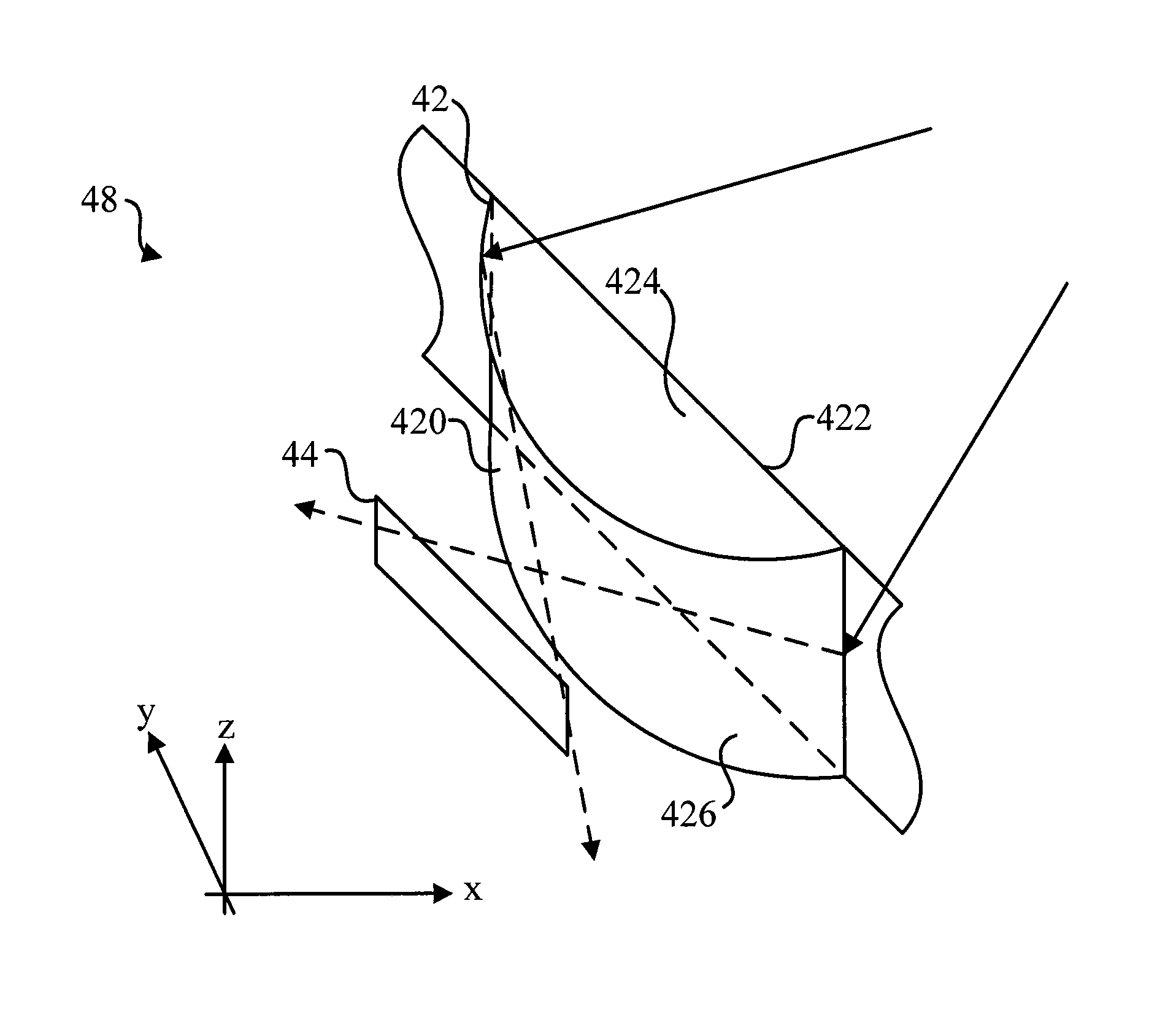
[0029]In this embodiment, the at least one light path unit 42 is disposed at a first side of the display unit 40 of the optical touch apparatus 4, and the at least one light path unit 42 is used to receive an incident light. It should be noticed that at least one refraction of ...


PUM


Abstract

The invention provides an optical touch apparatus. The optical touch apparatus includes at least one optical path unit and at least one light sensing unit. The at least one optical path unit is located on a first side of a display unit of the optical touch apparatus and used to receive at least one directional incident light, the at least one directional incident light is focused to form an image in an imaging region through at least one refraction in the at least one optical path unit. The at least one light sensing unit is located at a relative position of the at least one optical path unit, and used to generate a sensing result according to the image in the imaging region.

Description

BACKGROUND OF THE INVENTION[0001]1. Field of the Invention[0002]The present invention relates to optical touch, and more particularly, to an optical touch apparatus capable of receiving light signals of various directions in the display unit and reducing the imaging error of the image.[0003]2. Description of the Prior Art[0004]In recent years, with the continuous development of the touch image display technology, the conventional input function of the keyboard and mouse has been gradually replaced by various touch technological products. Accordingly, it is unnecessary to dispose keyboard on the electronic products or bring other input devices, so that the convenience and flexibility of the electronic products can be enhanced. In addition, since it is unnecessary to keep a region on the electronic product to dispose the keys, therefore, the size of the display monitor on the electronic product can be increased to provide the user better visual enjoyment and accuracy of the inputted d...

Claims


Application Information

Patent Timeline
Patent Type & Authority Patents(United States)
IPC IPC(8): G06F3/042G06F3/041
CPCG06F3/0428
Inventor HSU, LONGYEN, MENG-SHINWANG, WILLIAMCHOU, CHUNG-CHENG
Owner RAYDIUM SEMICON
Why Eureka
Try Eureka