Head and neck support device

a support device and head support technology, applied in the direction of chairs, sofas, transportation and packaging, etc., can solve the problems of insufficient cervical spine and head support, inconvenient use, and inconvenient us

Active Publication Date: 2014-12-02
MAJETTE MICHAEL S
View PDF29 Cites 48 Cited by
  • Summary
  • Abstract
  • Description
  • Claims
  • Application Information

AI Technical Summary

Benefits of technology

[0038]The present invention is defined by the appended claims with specific embodiments being shown in the attached drawings. For the purpose of summarizing the invention, the invention relates to an improved head and neck support device for positioning about a neck of an individual. The neck joins a head with a torso of the individual. The torso has a first shoulder and a second shoulder. A generally U-shaped pillow encircles the neck and is positioned adjacent to the first shoulder and the second shoulder of the individual. The generally U-shaped pillow has a rear pillow section, a first leg section and a second leg section. The head and neck support device comprises a rear supporting panel, a primary supporting panel and a secondary supporting panel. The rear supporting panel has an interior surface, an exterior surface, an upper edge, a lower edge, a first side edge and a second side edge. The primary supporting panel has an interior surface, an exterior surface, an upper edge, a lower edge, a front side edge and a back side edge. The secondary supporting panel has an interior surface, an exterior surface, an upper edge, a lower edge, a front side edge and a back side edge. The first side edge of the rear supporting panel is secured to the back side edge of the primary supporting panel for defining a primary generally L-shaped frame. The second side edge of the rear supporting panel is secured to the back side edge of the secondary supporting panel for defining a secondary generally L-sh...

Problems solved by technology

As a nerve exits the spinal canal it can be pinched causing moderate to severe pain.
Many of these supports suffer from the problem of shape distortion upon use.
As a user places the cervical spine and head cushion support in place and maintains the support in place, over a short period of time the support begins to change shape, resul...

Method used


Image

  • Head and neck support device
  • Head and neck support device
  • Head and neck support device

Examples


Embodiment Construction

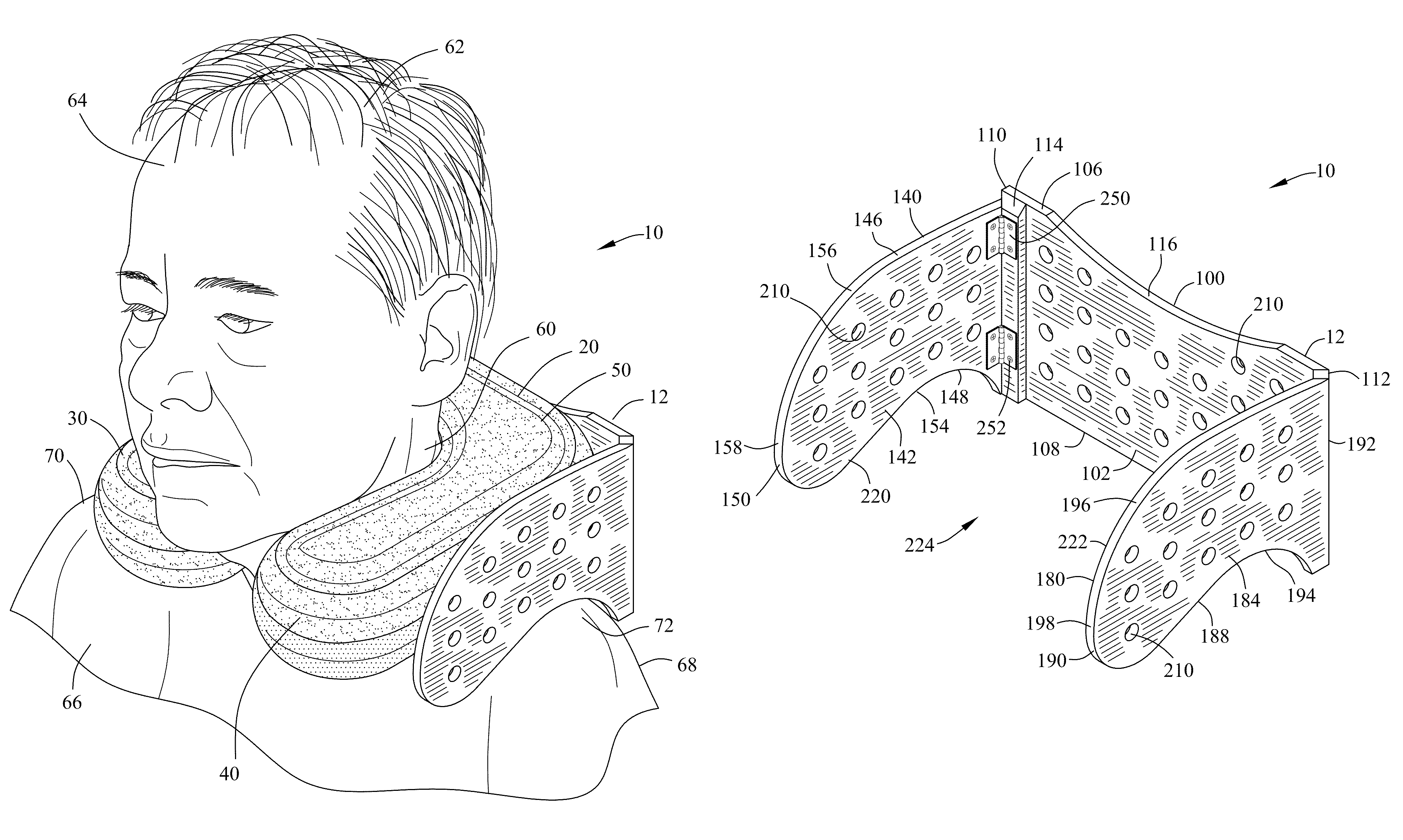
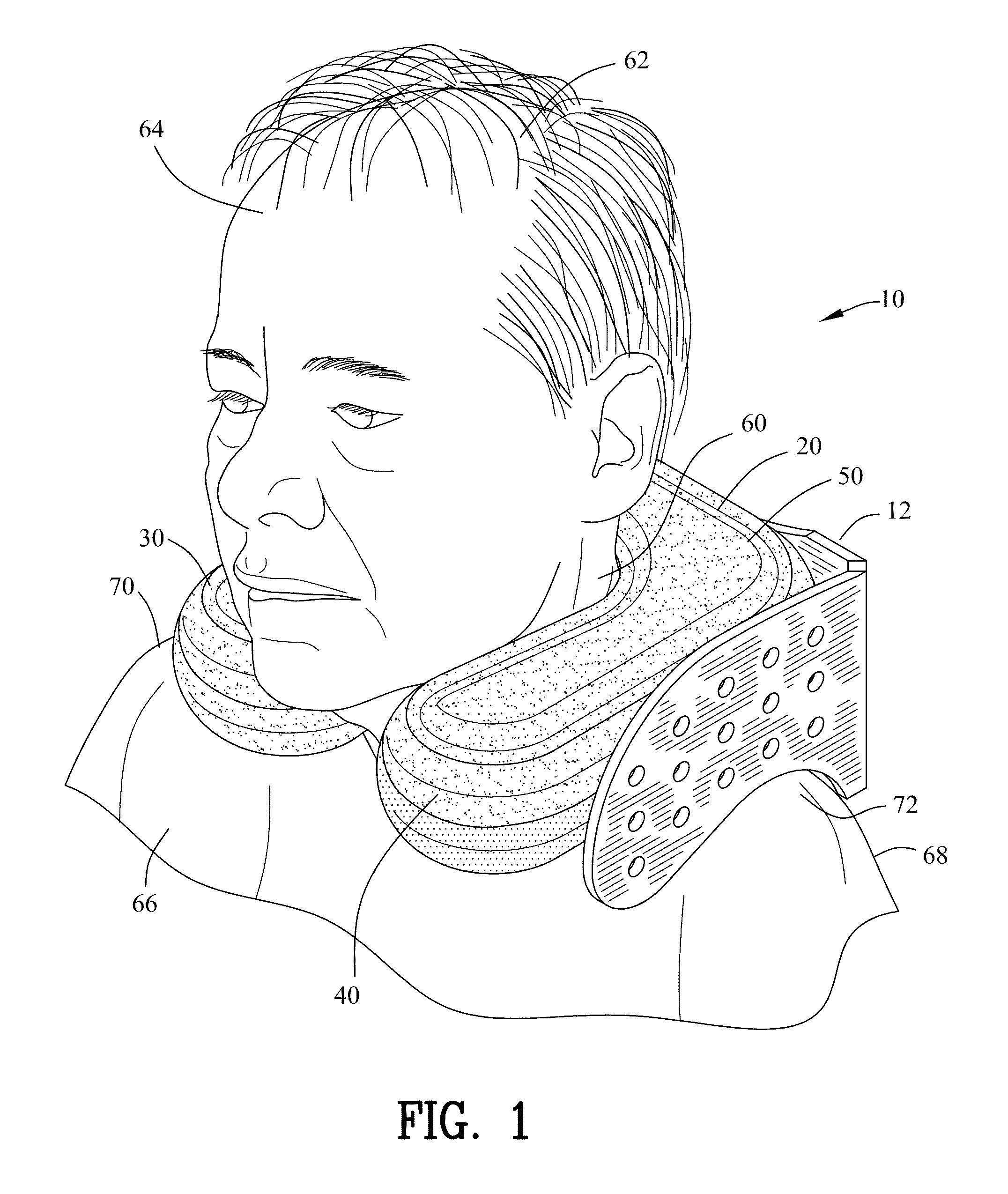
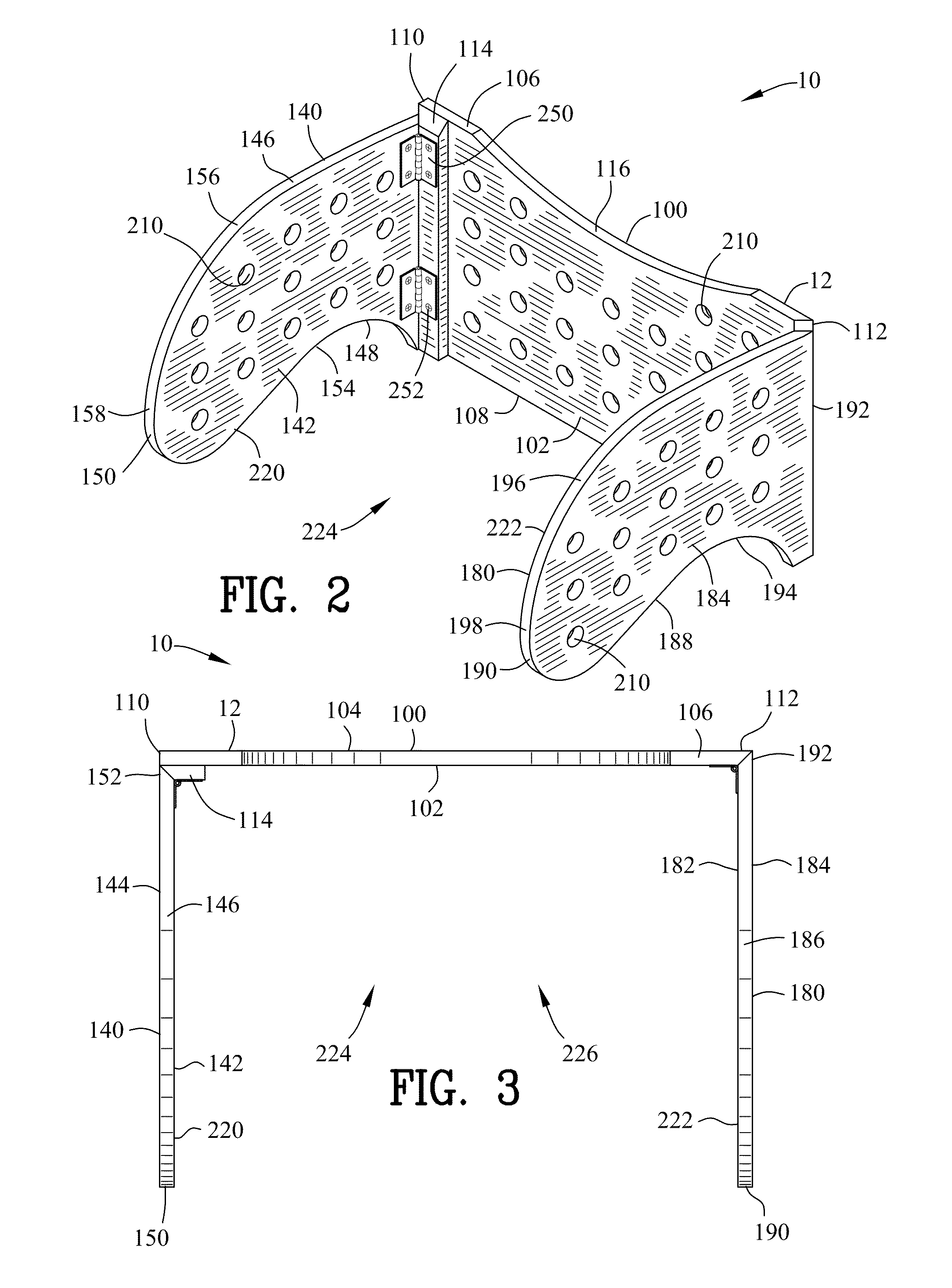
[0094]FIGS. 1-29A are various views of a head and neck support device 10. FIGS. 1-18A illustrate a first embodiment 12 of the head and neck support device 10. FIGS. 19-29A illustrate a second embodiment 14 of the head and neck support device 10.

[0095]FIGS. 9 and 10 illustrate prior art including a generally U-shaped pillow 20. The generally U-shaped pillow 20 has a rear pillow section 22, a first leg section 30 and a second leg section 40. The rear pillow section 22 defines an interior wall 24, an exterior wall 26, an upper wall 28 and a lower wall29. The first leg section 30 extends from the rear pillow section 22 and defines an interior wall 32, an exterior wall 34, an upper wall 36, a lower wall 38 and an end wall 39. Similarly, The second leg section 40 extends from the rear pillow section 22 and defines an interior wall 42, an exterior wall 44, an upper wall 46, a lower wall 48 and an end wall 49. Typically the generally U-shaped pillow 20 is constructed of a flexible fabric 50...


PUM


Abstract

A head and neck support device is disclosed for positioning about a neck of an individual. A generally U-shaped pillow encircles the neck. The head and neck support device comprises a rear supporting panel, primary supporting panel and a secondary supporting panel for defining a pillow enclosure frame and a pillow cavity. The pillow cavity receives the generally U-shaped pillow. The primary supporting panel applies a first opposing force for supporting the head and neck in a generally vertical position. The secondary supporting panel applies a second opposing force for supporting the head and neck in a generally vertical position.

Description

CROSS-REFERENCE TO RELATED APPLICATIONS[0001]This application claims benefit of U.S. Patent Provisional application Ser. No. 61 / 628,313 filed Oct. 28, 2011. All subject matter set forth in provisional application Ser. No. 61 / 628,313 is hereby incorporated by reference into the present application as if fully set forth herein.BACKGROUND OF THE INVENTION[0002]1. Field of the Invention[0003]This invention relates to a support device and more particularly to a head and neck support device.[0004]2. Background of the Invention[0005]The cervical spine comprises seven vertebrae which begin at the base of the skull. These vertebrae are smaller in size than other spinal vertebrae. The cervical spine supports the skull and enables the skull to rotate side to side as well as to bend forward and backward. Additionally the cervical spine protects the spinal cord from injury. A highly complex system comprising ligaments, tendons and muscles supports and stabilizes the cervical spine, and prevents ...

Claims


Application Information

Patent Timeline
IPC IPC(8): A47G9/10A47C7/38A47C16/00
CPCA47G9/1081A47C7/383
Inventor MAJETTE, MICHAEL S.
Owner MAJETTE MICHAEL S
Why Eureka
Try Eureka