Pedal-driven roller board

a technology of roller boards and pedals, applied in the field of roller boards, can solve the problems of wasting energy, wasting time, and wasting physical energy, and achieve the effect of easy change of speed

Inactive Publication Date: 2014-12-02
KIM JI HOON
View PDF17 Cites 4 Cited by
  • Summary
  • Abstract
  • Description
  • Claims
  • Application Information

AI Technical Summary

Benefits of technology

[0012]According to a pedal-driven roller board according to the present invention, it is configured to enable a roller board to move in such a way that the gears can be driven as the reciprocation movements of the pedal disposed at a board are converted to a rotational movement unless a user kicks the ground, and a user can easily change the speed with the aid of a transmission and can do a muscle exercise as the user steps on the pedals.

Problems solved by technology

However, since the conventional roller board is driven with one foot kicking the ground, a kid or a child whose physical frame is not fully grown might suffer from the deformed physical growths, and when a user uses it for a long time, a lot of physical energy is consumed.
In particular, when it is used on a slope, more energy is needed, so there are lots problems to use it for a long time and to enjoy with it.

Method used


Image

  • Pedal-driven roller board
  • Pedal-driven roller board
  • Pedal-driven roller board

Examples


Embodiment Construction

[0018]Hereinafter the preferred embodiments of the present invention will be described with reference to the accompanying drawings. The elements having the same functions and construction will be given the same reference numerals.

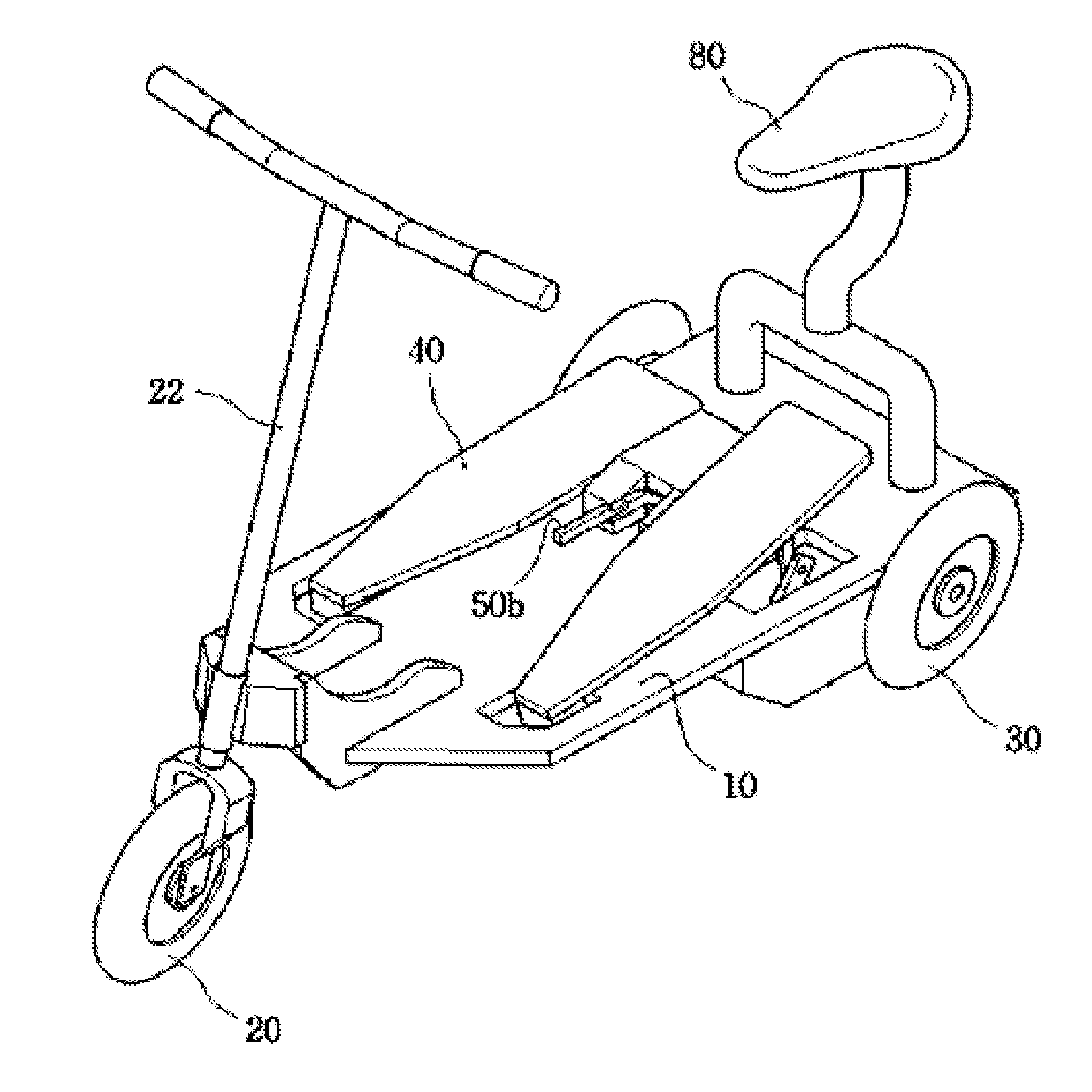
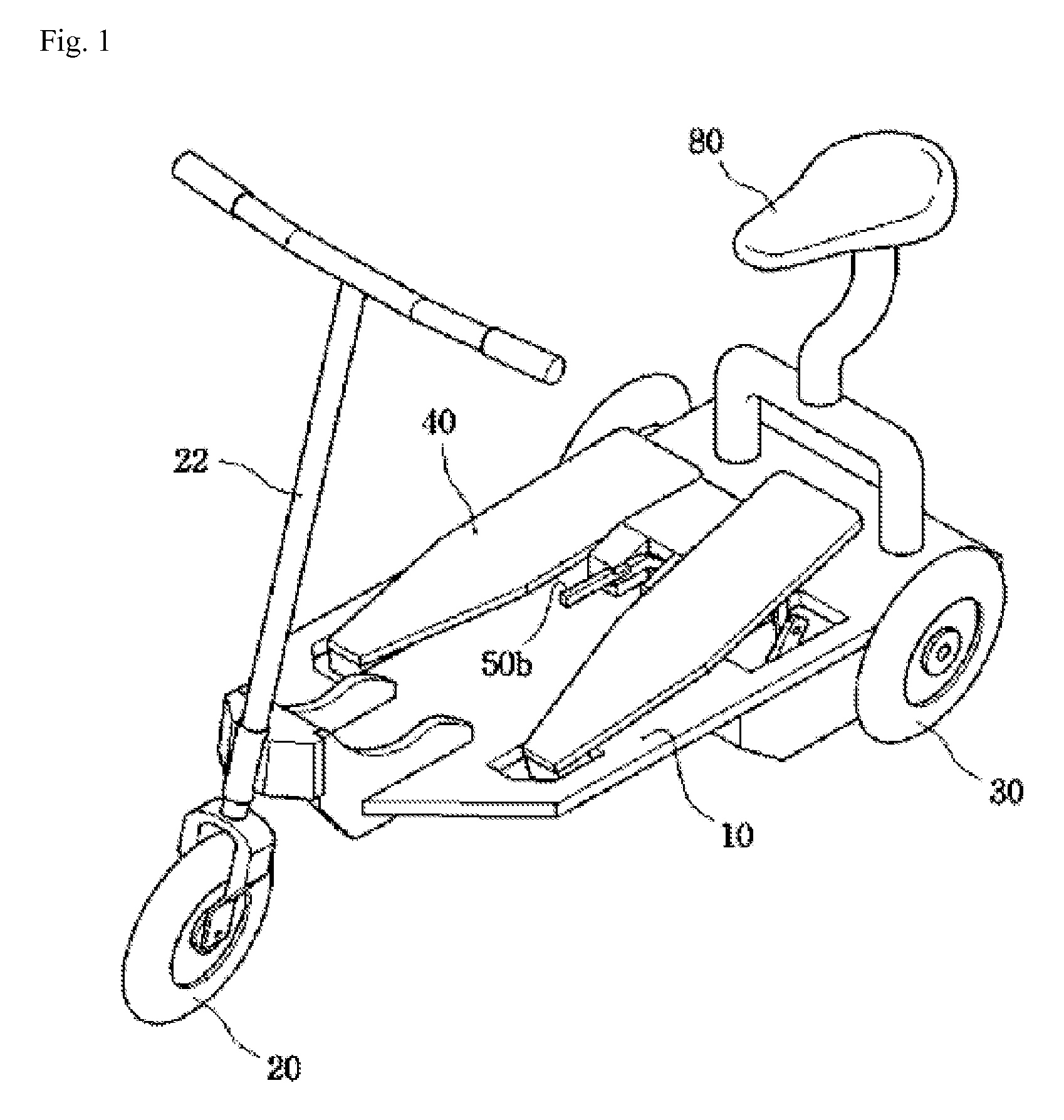
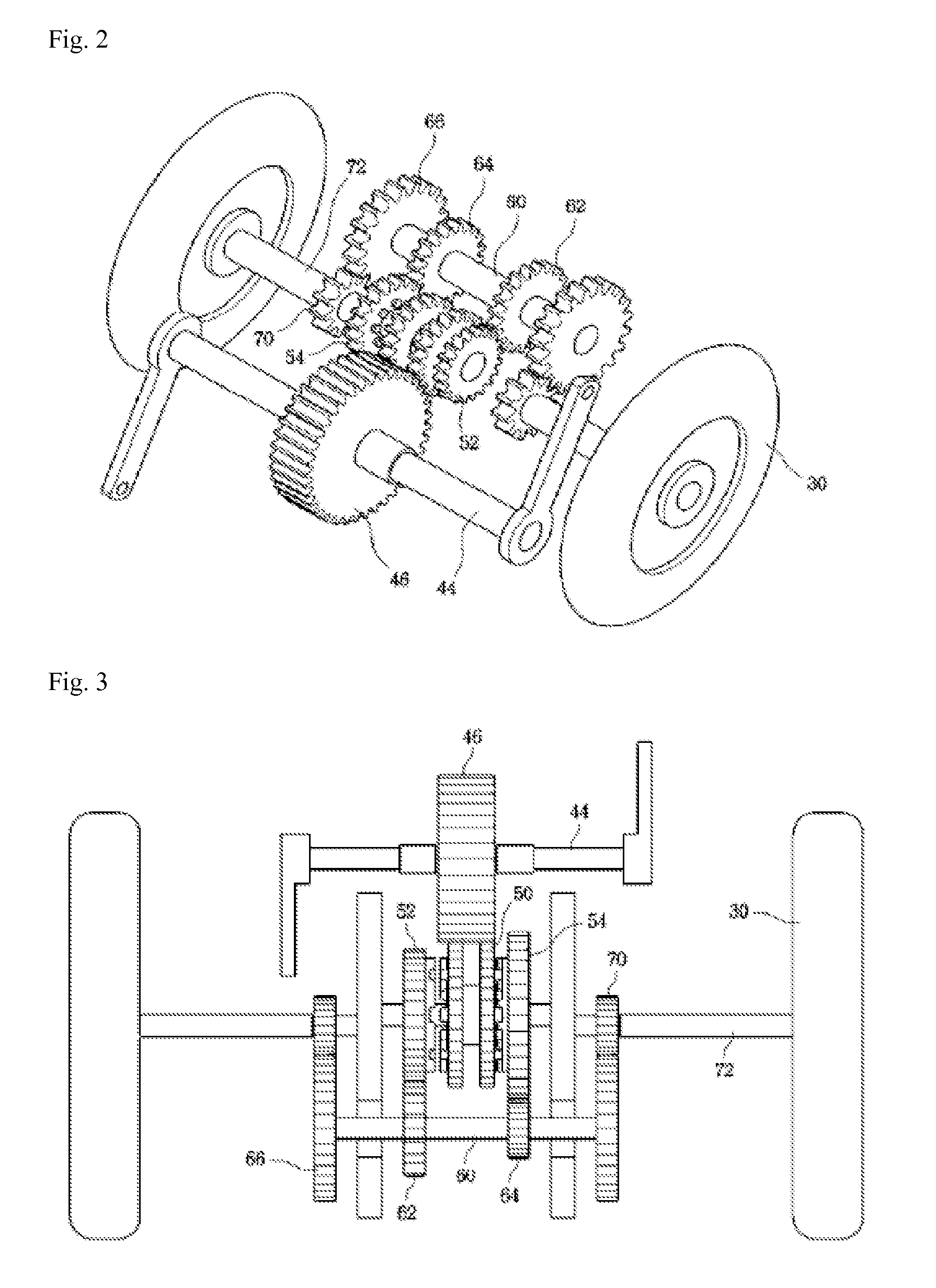
[0019]FIG. 1 is a perspective view illustrating a pedal-driven roller board according to the present invention. FIG. 2 is a perspective view illustrating a driving force transfer device for a penal-driven roller board according to the present invention. FIG. 3 is a plane view illustrating a driving force transfer device for a pedal-driven roller board according to the present invention. FIG. 4 is a view illustrating a state that a driving gear rotates by means of a pedal according to the present invention. FIGS. 5a and 5d are views illustrating a clutch gear and a speed change gear according to the present invention.

[0020]First of all, the term “front side” in the present invention represents a direction that the roller board moves forward and “rear side” r...


PUM


Abstract

The present invention relates to a roller board, and more particularly, to a pedal-driven roller board that converts a reciprocating motion of pedals formed on the board into a rotational motion to drive a gear, so that a user can drive the board without kicking the ground. Furthermore, the pedal-driven roller board includes a derailleur, so that a user can conveniently control the speed of the pedal-driven roller board. Moreover, a user can develop and strengthen his / her muscles by pedaling the pedal-driven roller board. To this end, a pedal-driven roller board according to the present invention includes: a handle disposed at the front side of a board to steer a front wheel; a rear wheel at the rear side of the board; and two pedals formed on the top surface of the board to drive the rear wheel. Further, the pedal-driven roller board includes: a link having an end hinged to the bottom surface of a pedal; a driving gear formed on an end of a crankshaft connected through a shaft to the other end of the link to convert a reciprocating motion of the pedal into a rotational motion; a clutch gear engaged with the driving gear to rotate, and selectively connected to one of either a first speed gear or a second speed gear to rotate same; a first connecting gear and a second connecting gear, which rotatably engage with the first speed gear and the second speed gear, respectively, and are installed on an end of a connecting shaft; a transmission gear installed on both ends of the connecting shaft and rotated by torque transmitted through the connecting shaft from the first and second connecting gears; and a rotation gear engaging with the transmission gear to rotate, and connected to the rear wheel through a rotation shaft to transmit the torque from the transmission gear to the rear wheel.

Description

TECHNICAL FIELD[0001]The present invention relates to a roller board, and in particular to a pedal-driven roller board which is configured to enable a roller board to move in such a way that the gears can be driven as the reciprocation movements of the pedal disposed at a board are converted to a rotational movement unless a user kicks the ground, and a user can easily change the speed with the aid of a transmission and can do a muscle exercise as the user steps on the pedals.BACKGROUND ART[0002]Generally speaking, a roller board is configured for a user to ride on a board with wheels at the front and rear sides, respectively, and to move forward while kicking the ground with one foot.[0003]The above mentioned roller board is widely used because it is portable and is easy to store and anyone can easily use it.[0004]However, since the conventional roller board is driven with one foot kicking the ground, a kid or a child whose physical frame is not fully grown might suffer from the de...

Claims


Application Information

Patent Timeline
Patent Type & Authority Patents(United States)
IPC IPC(8): B62M1/26B62M1/30B62K5/02B62M1/00B62M1/24B62K3/00
CPCB62M1/26B62K5/02B62K3/002B62M1/30
Inventor KIM, JI HOON
Owner KIM JI HOON
Why Eureka
Try Eureka