Seat adjustment device, and vehicle seat device with the seat adjustment device

a technology for vehicle seats and adjustment devices, which is applied to chairs, furniture parts, movable seats, etc., can solve the problems increase the thickness of plates, and achieve the effects of enlargement of the entire apparatus, increased plate thickness, and sufficient strength

Inactive Publication Date: 2014-12-02
AISIN SEIKI KK
View PDF15 Cites 57 Cited by
  • Summary
  • Abstract
  • Description
  • Claims
  • Application Information

AI Technical Summary

Benefits of technology

[0007]In patent document 1, the seat adjustment device is formed by the link mechanism. Thus, sufficient strength has to be ensured at all links and pivot shafts of the links. This increases the thickness of plates and results in enlargement of the entire apparatus.
[0009]It is an object of the present invention to provide a seat adjustment device capable of reducing moment strength required for a rotation adjustment mechanism for adjusting a pivot angle of a first seat member and a second seat member that are pivotally coupled to each other, and to provide a vehicle seat apparatus including such a seat adjustment device.

Problems solved by technology

This increases the thickness of plates and results in enlargement of the entire apparatus.

Method used


Image

  • Seat adjustment device, and vehicle seat device with the seat adjustment device
  • Seat adjustment device, and vehicle seat device with the seat adjustment device
  • Seat adjustment device, and vehicle seat device with the seat adjustment device

Examples


first embodiment

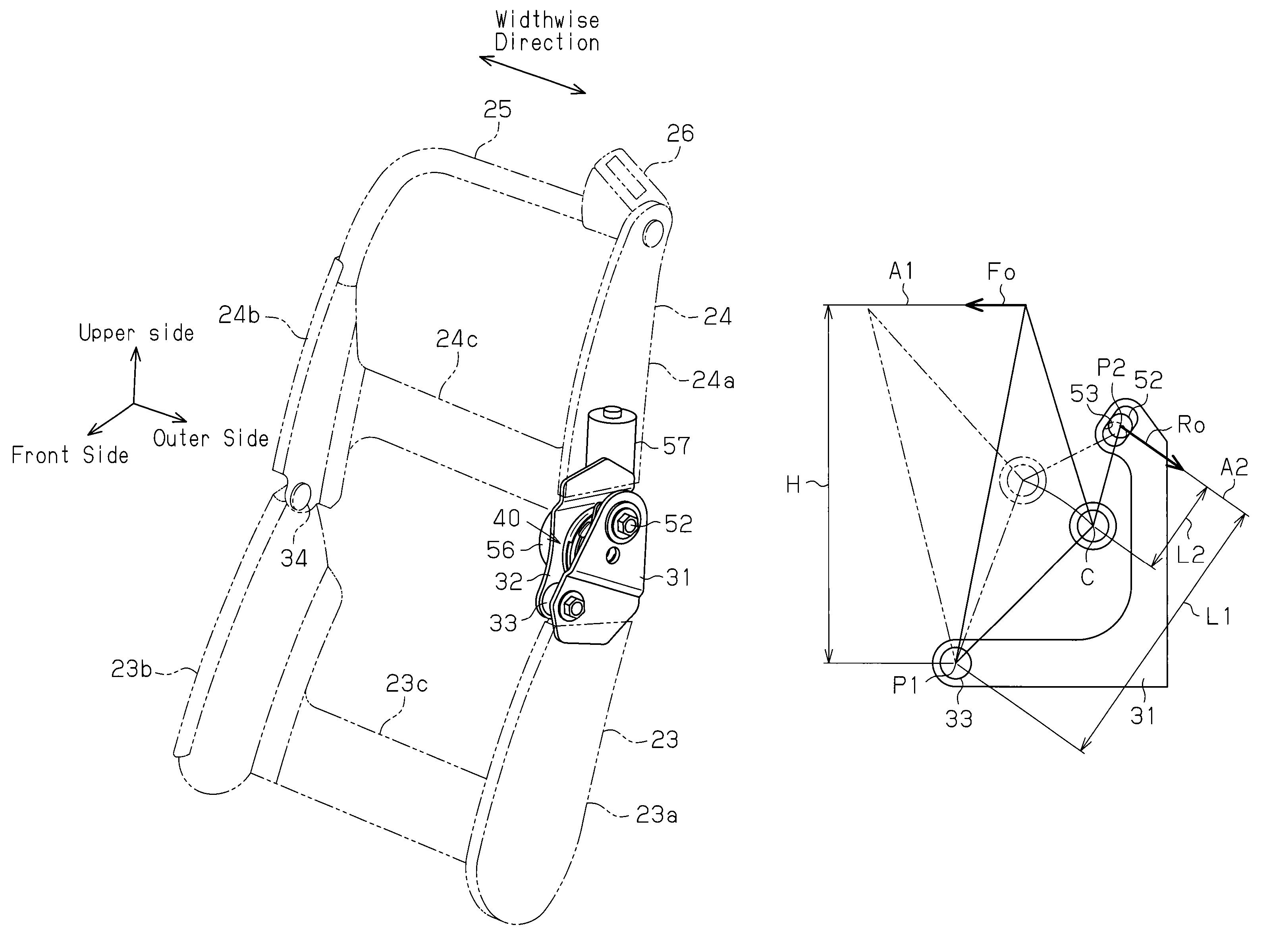
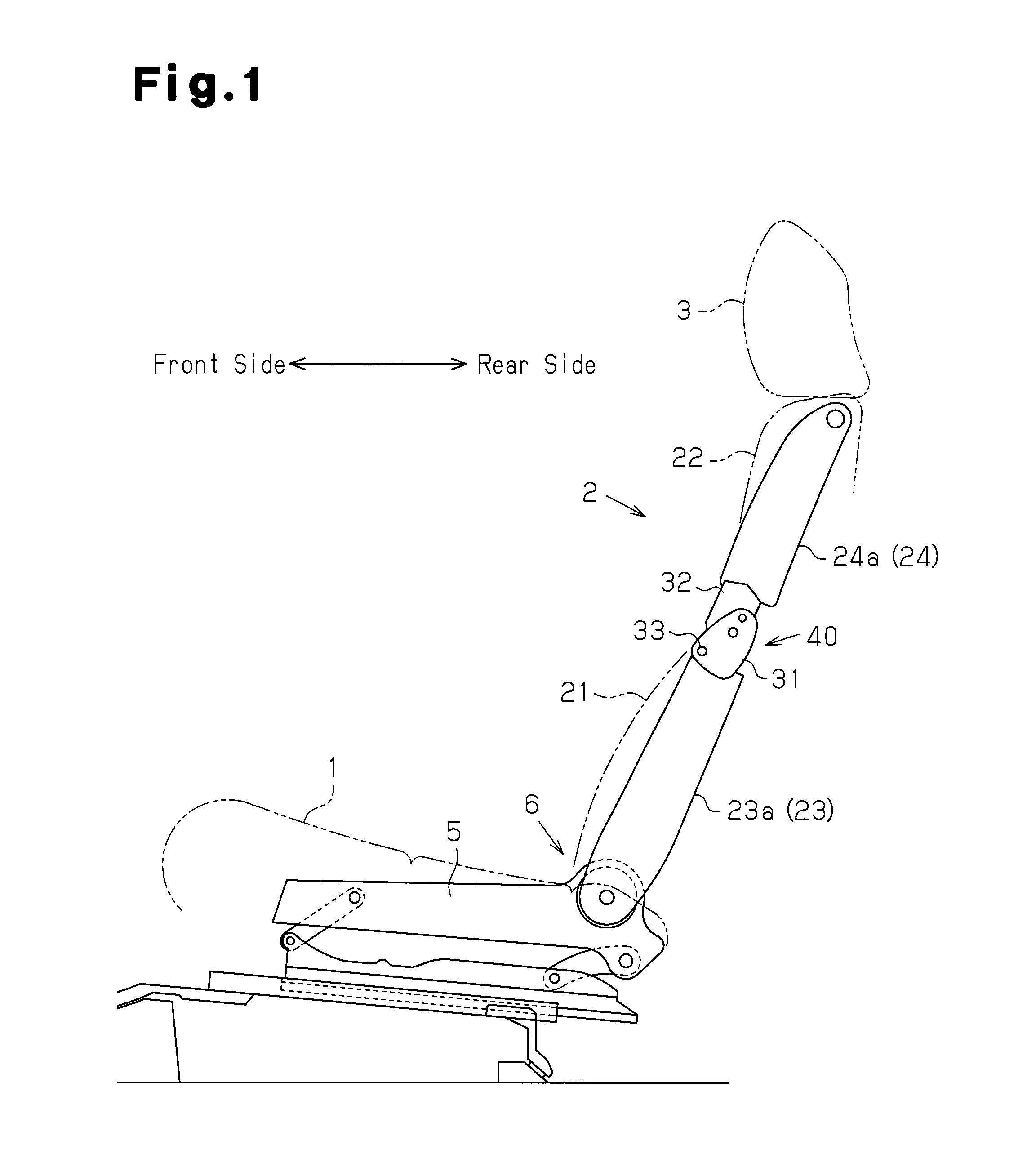
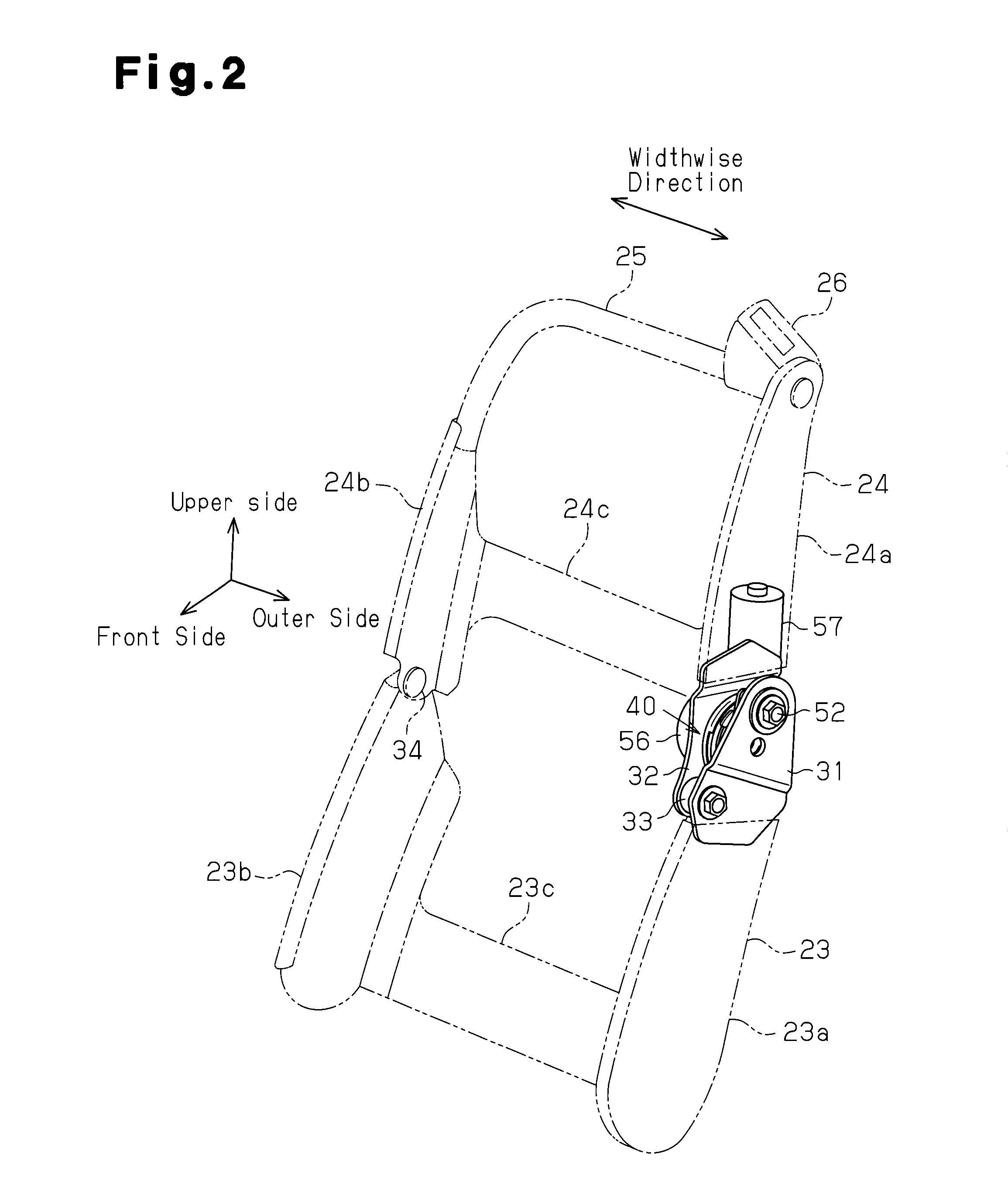
[0020]A first embodiment of the present invention will be described with reference to FIG. 1. As shown in FIG. 1, a vehicle seat apparatus, which is mounted as a front seat in a vehicle such as an automobile, for example, includes a seat cushion 1, which forms a seating portion, having a rear end that supports a lower end of a seat back 2, which forming a backrest, so that the seat back 2 is tiltable in a front to rear direction. The seat back 2 is divided into a lower seat back 21, which is capable of supporting the waist of a vehicle occupant, and an upper seat back 22, which is capable of supporting a blade bone of the vehicle occupant. The seat back 2 is supported by the rear end of the seat cushion 1 at a lower end of the lower seat back 21 so that the seat back 2 is tiltable in the front to rear direction. A headrest 3 for supporting the head of a vehicle occupant is arranged on an upper end of the seat back 2 (upper seat back 22) so that the headrest 3 is movable upward and d...

second embodiment

[0059]A second embodiment of the present invention will now be described with reference to FIG. 6. In the second embodiment, only the structure for absorbing changes in the eccentric amount of the axis of the pivot portion 43 relative to the axis of the hinge shaft 33 is modified from the first embodiment. Therefore, similar components will not be described in detail.

[0060]As shown in FIG. 6, a lower member 61, which serves as a second seat member and a lower frame formed from metal plate, for example, is welded and fixed to an upper end of an outer surface in the widthwise direction of the lower side frame 23a. A circular bearing hole 62, which serves as a bearing portion, is formed in an upper end of the lower member 61. The bearing hole 62 opens toward the guide pin 52 and has an inner diameter that is sufficiently larger than an outer diameter of the guide pin 52 (shaft portion 52b). An eccentric bushing 63, which serves as a shaft member, is attached to the bearing hole 62. The...

third embodiment

[0072]A third embodiment of the present invention will now be described with reference to FIG. 8. In the third embodiment, only the structure for absorbing changes in the eccentric amount of the axis of the pivot portion 43 relative to the axis of the hinge shaft 33 is modified from the first embodiment. Therefore, similar components will not be described in detail.

[0073]As shown in FIG. 8, a lower member 71, which serves as a second seat member and a lower frame formed from metal plate, for example, is welded and fixed to the upper end of the outer surface in the widthwise direction of the lower side frame 23a. The lower member 71 is pivotally coupled to an elongated rod member 72 formed from metal plate, for example. That is, a circular coupling hole 73 is formed in the lower member 71 behind the bearing hole 31a. A substantially stepped cylindrical support pin 74 is fixed to the coupling hole 73. The support pin 74 extends through the coupling hole 73 in the widthwise direction. ...


PUM


Abstract

A seat adjustment device adjusts the pivoting angle formed by a first seat member and a second seat member. A hinge shaft connects at a first connection point, the first seat member, and the second seat member. An arm section and a connection mechanism are connected at a second connection point. The positions of the axes of the first connection point, the second connection point, and a pivoting section are set in such a manner that, when a load is applied to the front end of either the first seat member or the second seat member, the distance from the second connection point to the axis of the pivoting section is less than the distance from the first connection point to the second connection point with respect to the direction perpendicular to the line of action of a load applied to the second connection point.

Description

TECHNICAL FIELD[0001]The present invention relates to a seat adjustment device that adjusts a pivot angle between a first seat member and a second seat member, which are pivotally coupled to each other, and a vehicle seat apparatus that includes a seat back divided into an upper portion and a lower portion in a vertical direction and allows for the upper portion to be tilted relative to the lower portion by the seat adjustment device in a front to rear direction.BACKGROUND ART[0002]Various types of vehicle seat apparatuses have been proposed in the prior art (e.g., patent documents 1 and 2). A seat back of these seat apparatuses is divided into a lower portion, capable of supporting the waist of a vehicle occupant sitting on the seat apparatus, and an upper portion, capable of supporting a blade bone of the vehicle occupant. A seat adjustment device couples an upper frame (first seat member) forming the framework for the upper portion of the seat back and a lower frame (second seat ...

Claims


Application Information

Patent Timeline
Patent Type & Authority Patents(United States)
IPC IPC(8): B60N2/68B60N2/16B60N2/02B60N2/22A47C7/46B60N2/225
CPCB60N2/688B60N2/1615B60N2/0232B60N2002/024B60N2/2252B60N2/2254B60N2/2222B60N2/02258B60N2/02246
Inventor ITO, SADAO
Owner AISIN SEIKI KK
Why Eureka
Try Eureka