Implantable lead bandstop filter employing an inductive coil with parasitic capacitance to enhance MRI compatibility of active medical devices

a technology of inductive coils and active medical devices, which is applied in the field of inductive coilparasitic capacitance bandstop filter assemblies, can solve the problems of distal tip electrode overheating at inappropriate times, presenting a very high impedance, etc., and achieves rapid imagery

Active Publication Date: 2014-12-02
WILSON GREATBATCH LTD
View PDF278 Cites 5 Cited by
  • Summary
  • Abstract
  • Description
  • Claims
  • Application Information

AI Technical Summary

Benefits of technology

[0043]The Qi of the inductor may be relatively minimized (or maximized) and the Qc of the capacitor may be relatively maximized (or minimized) to reduce and / or control the overall Q of the bandstop filter. For example, the Qi of the inductor is relatively minimized by increasing / controlling the resistive loss in the inductor, and the Qc of the capacitor is relatively maximized by raising or lowering the equivalent series resistance (ESR) of the capacitor (in this case, the dielectric loss tangent of the inductor coil insulation is important). This reduces the overall Q of the bandstop filter in order to broaden its 3 dB and 10 dB bandwidth points and thereby attenuate current flow through the lead along a range of selected frequencies. The range of selected frequencies may include a plurality of MRI RF pulsed frequencies.
[0047]In summary, the overall Q of the bandstop filter circuit may be reduced by increasing the Qi of the inductor and reducing the Qc of the capacitor. In this regard, minimizing resistive loss in the inductor maximizes the Qi of the inductor, and raising the equivalent series resistance of the capacitor minimizes the Qc of the capacitor. Conversely, the overall Q of the bandstop filter may be reduced by decreasing the Q of the inductor and increasing the Q of the capacitor. The overall Q of the bandstop filter could also be reduced by reducing the Q of both the inductor and the capacitor.
[0048]The preferred embodiment is to reduce the overall Q of the bandstop filter circuit which widens the 3 dB and 10 dB bandwidths to attenuate current flow through the lead along a range of selected RF frequencies. As discussed herein, the range of selected frequencies may include a plurality of MRI RF pulse frequencies.
[0051]At first glance, it seems contradictory when one can have as narrow as a 10 kHz 10 dB bandwidth. This has to do with the impedance of the bandstop filter. There is a considerable impedance or insertion loss safety margin for a typical bandstop filter, which may have as much as 2000 ohms impedance at its resonant center frequency. In other words, even 15 or 20 dB down, it may provide adequate impedance and adequate protection to protect a lead conductor and / or its distal electrode from RF induced current overheating in an MRI environment. The amount of impedance actually needed from the bandstop filter is subject to a number of variables including the implanted lead trajectory, the implanted lead length, the implanted lead characteristics, the characteristics of the body tissue being imaged, and the like. By way of example, for a particular bandstop filter that had a 10 kHz 3 dB bandwidth with an attenuation of 42 dB at its resonant center frequency, the same filter may have a 20-dB bandwidth of 270 kHz which means that it would provide at least 22 dB of attenuation over the entire gradient modified RF pulse frequency range for a particular MRI scanner. In most cases, 20 dB of attenuation would be adequate to prevent an implanted lead and / or its distal electrode from overheating. The range of frequencies comprises a plurality of MRI RF pulsed frequencies. Moreover, the bandstop filter is designed to have an overall circuit Q wherein the resultant 3 dB bandwidth is at least, in some embodiments, 10 kHz, in others at least 100 kHz, and in still others at least 0.5 MHz.

Problems solved by technology

It is also well known that when the bandstop filter is at its resonant frequency, it will present a very high impedance.
However, a major concern is the overheating of the distal Tip electrode at inappropriate times because of the induced currents from the MRI system.

Method used


Image

  • Implantable lead bandstop filter employing an inductive coil with parasitic capacitance to enhance MRI compatibility of active medical devices
  • Implantable lead bandstop filter employing an inductive coil with parasitic capacitance to enhance MRI compatibility of active medical devices
  • Implantable lead bandstop filter employing an inductive coil with parasitic capacitance to enhance MRI compatibility of active medical devices

Examples


Embodiment Construction

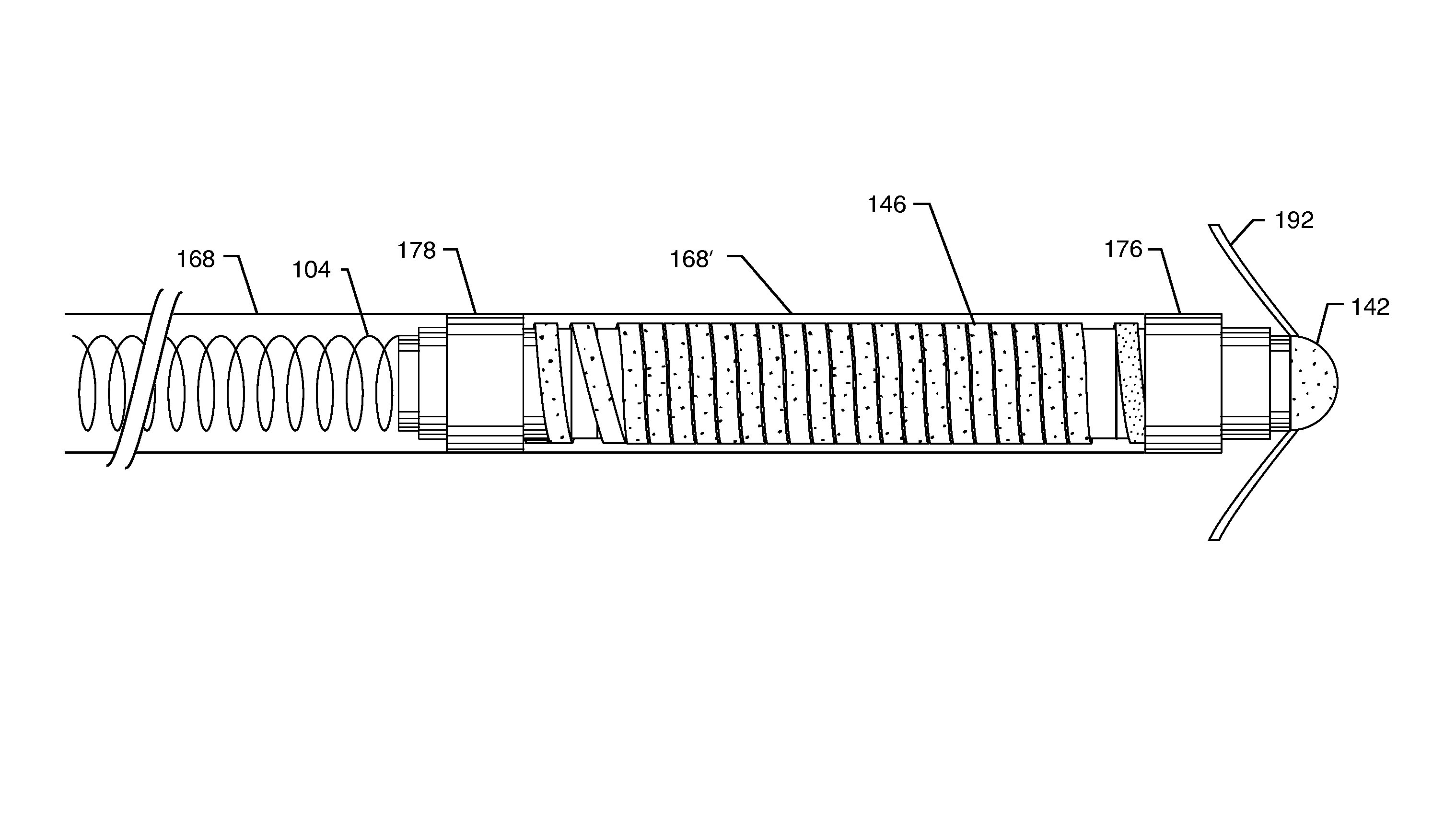
[0113]The present invention is directed to medical lead systems comprising an implantable lead having a proximal end and an electrode in contact with biological cells at a distal end. At least one bandstop filter is associated with a lead conductor for attenuating current flow through the lead over a range of frequencies. The bandstop filter has an overall circuit Q wherein the resultant 3 dB bandwidth is at least 10 kHz and where the bandstop filter comprises a capacitance in parallel with an inductance, wherein values of capacitance and inductance are selected such that the bandstop filter is resonant at a selected center frequency.

[0114]As used herein, the term “bandwidth” refers to an attenuation or insertion loss plot measured (or calculated) in a balanced 50-ohm system (50-ohm source and load impedance). The best method is by swept measurements in a 50-ohm spectrum or network analyzer system with proper attention to “thru” and “short” calibrations. The most accurate measuremen...


PUM


Abstract

A medical lead system includes at least one bandstop filter for attenuating current flow through the lead across a range of frequencies. The bandstop filter has an overall circuit Q wherein the resultant 3 dB bandwidth is at least 10 kHz. The values of capacitance and inductance of the bandstop filter are selected such that the bandstop filter is resonant at a selected center frequency or range of frequencies. Preferably, the bandstop filter has an overall circuit Q wherein the resultant 10 dB bandwidth is at least 10 kHz. Such bandstop filters are backwards compatible with known implantable deployment systems and extraction systems.

Description

CROSS-REFERENCE TO RELATED APPLICATIONS[0001]This application is a continuation-in-part of U.S. application Ser. No. 12 / 170,811, filed on Jul. 10, 2008, which is a divisional of U.S. application Ser. No. 11 / 423,073, filed on Jun. 8, 2006, now U.S. Pat. No. 8,244,370.FIELD OF THE INVENTION[0002]This invention relates generally to novel inductive coil-parasitic capacitance bandstop filter assemblies, particularly of the type used in the implantable leads of active medical devices (AMDs) such as cardiac pacemakers, cardioverter defibrillators, neurostimulators, externally worn Holter monitors and the like, which decouple lead wires and / or electronic components of the medical device from undesirable electromagnetic interference (EMI) signals at a selected center frequency or range of frequencies, such as the RF pulsed fields of Magnetic Resonance Imaging (MRI) equipment.BACKGROUND OF THE INVENTION[0003]Compatibility of cardiac pacemakers, implantable defibrillators and other types of ac...

Claims


Application Information

Patent Timeline
Patent Type & Authority Patents(United States)
IPC IPC(8): A61N1/37A61B19/00A61B5/055A61B18/14A61B18/00H03H1/00H03H7/01A61N1/08A61N1/05
CPCA61B18/1492H03H7/1766A61B2019/5236A61N1/3718A61B2018/00839H03H2001/005H03H1/0007H03H2007/013H03H2001/0042A61N1/056A61N1/0551A61N1/05A61N2001/086A61B2090/374A61N1/086
Inventor STEVENSON, ROBERT A.HALPERIN, HENRY R.LARDO, ALBERT C.DABNEY, WARREN S.KONDABATNI, KISHORE KUMARFRYSZ, CHRISTINE A.JOHNSON, ROBERT SHAWNMOSCHIANO, HOLLY NOELLEMUFFOLETTO, BARRY C.
Owner WILSON GREATBATCH LTD
Why Eureka
Try Eureka