Flow measurement device

a flow measurement and flow measurement technology, applied in liquid/fluent solid measurement, instruments, machines/engines, etc., can solve the problems of increasing current consumption, unable to realize inability to measure ultrasonic wave propagation time using the zero crossing point preceding the trigger level, etc., to achieve highly accurate flow measurement, reduce the error contained in the propagation time or the arrival time of the measured ultrasonic wave, and save power

Active Publication Date: 2014-12-02
PANASONIC CORP
View PDF12 Cites 5 Cited by
  • Summary
  • Abstract
  • Description
  • Claims
  • Application Information

AI Technical Summary

Benefits of technology

[0021]The flow measurement device of the invention uses consecutively at least two or more zero crossing point arrival times of the ultrasonic wave received before the trigger level, finds an average value thereof, and can measure the arrival time of the ultrasonic wave. Thus, if an offset, etc., is superposed, it can be canceled at the rising zero point and the falling zero point. An average value of zero crossing points is used, whereby an error contained in the propagation time or the arrival time of the measured ultrasonic wave can be lessened and while highly accurate flow measurement is realized, power saving operation can be realized.
[0019]According to the configuration, the propagation time of the ultrasonic wave propagating between the upstream ultrasonic vibrator and the downstream ultrasonic vibrator, namely, the arrival time of the ultrasonic wave can be measured by using consecutively at least two or more zero crossing point arrival times of the ultrasonic wave received before the trigger level and finding an average value thereof, an error contained in the propagation time of the ultrasonic wave is lessened and while highly accurate flow measurement is realized, power saving operation can be realized.

Problems solved by technology

Therefore, it is impossible to measure the ultrasonic wave propagation time using the zero crossing point preceding the trigger level.
Thus, an uncertain time is contained in the ultrasonic wave arrival time, an error may occur, and the measurement device has a problem in that it cannot realize highly accurate flow measurement.
Further, long-time measurement exceeding the essential arrival time means extra operation of the measurement device and thus the measurement device has also a problem of an increase in the current consumption.

Method used


Image

  • Flow measurement device
  • Flow measurement device
  • Flow measurement device

Examples


embodiment 1

(Embodiment 1)

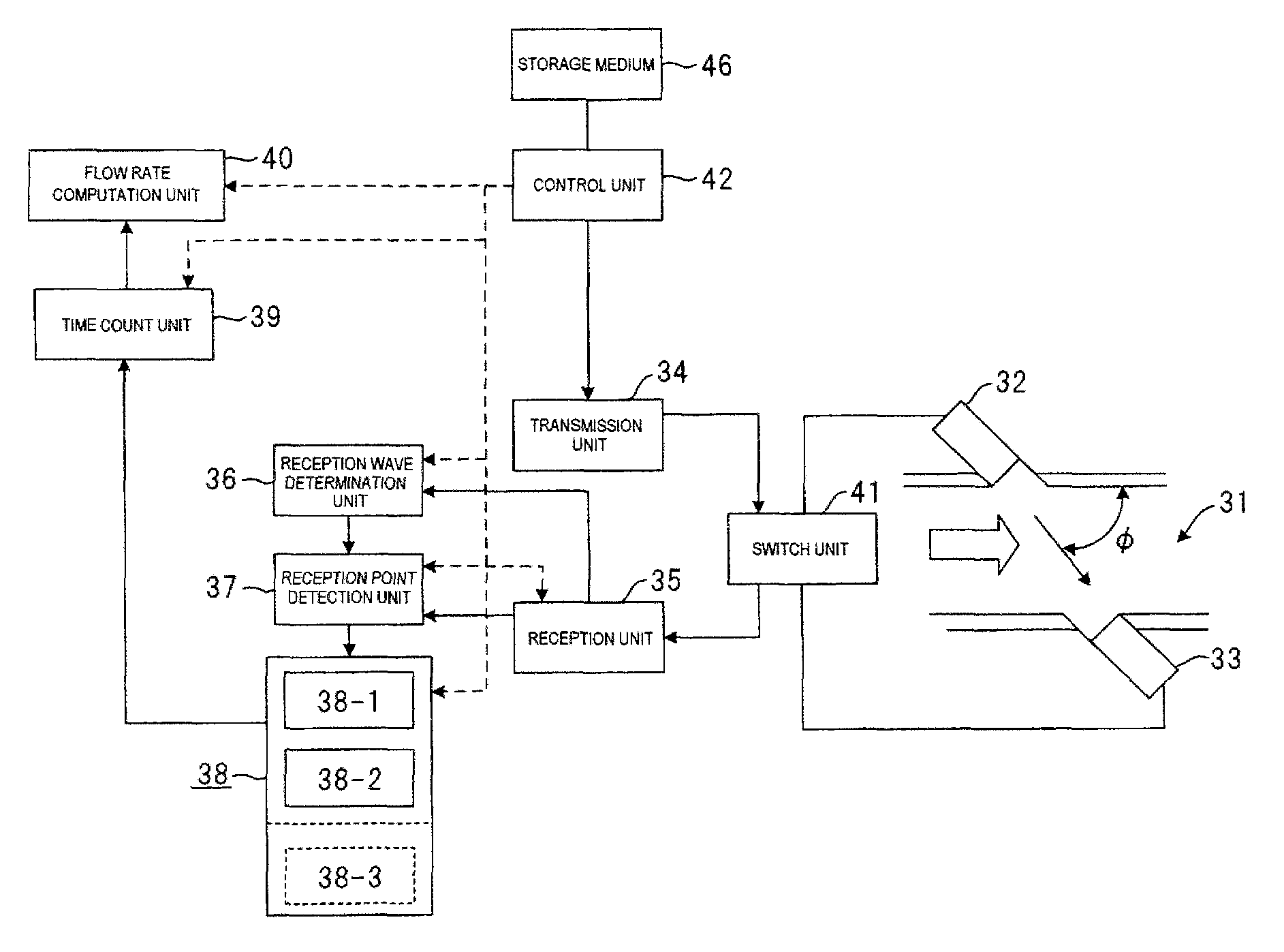
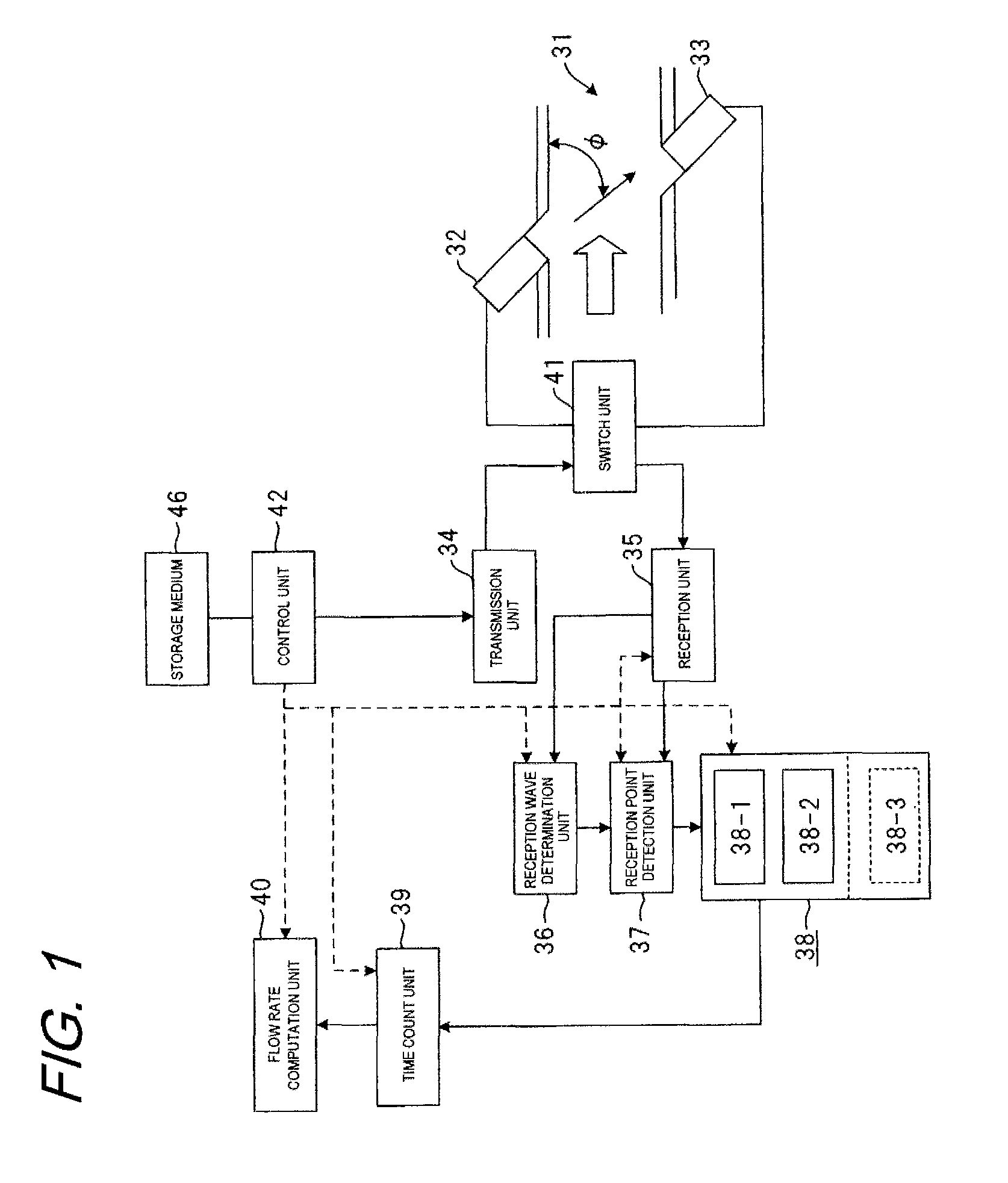
[0074]In FIG. 1, an ultrasonic flowmeter of the embodiment forming a flow measurement device has a flow path 31 where a measured fluid flows and a first vibrator 32 and a second vibrator 33 placed in the flow path 31 for transmitting and receiving an ultrasonic wave. It also has a transmission unit 34 for driving the first vibrator 32 and the second vibrator 33, a reception unit 35 for receiving reception signals of the first vibrator 32 and the second vibrator 33 and amplifying the signals, a reception wave determination unit 36 for outputting a signal when the signal of the reception unit 35 becomes a predetermined value, and a reception point detection unit 37 for outputting a signal when the signal of the reception unit 35 becomes a predetermined range. It also has two reception point storage units 38 for storing output of the reception point detection unit 37, a time count unit 39 for counting the propagation time of an ultrasonic wave signal propagating between t...

embodiment 2

(Embodiment 2)

[0164]A flow measurement device of embodiment 2 will be discussed. The flow measurement device differs from the flow measurement device of embodiment 1 in that it uses a storage medium 46 having a program for causing a computer to function to ensure the operation of control unit 42 for controlling at least one of vibrators 32 and 33, a transmission unit 34, a reception unit 35, a reception wave determination unit 36 for outputting a signal when a signal of the reception unit 35 becomes a predetermined value, a reception point detection unit 37 for outputting a signal when a signal of the reception unit 35 becomes a predetermined range, reception point storage units 38 for storing output of the reception point detection unit 37, a time count unit 39 for counting the propagation time of an ultrasonic wave signal propagating between the vibrators using each signal of the reception point storage units 38, a flow rate computation unit 40 for calculating the flow rate based ...

embodiment 3

(Embodiment 3)

[0169]In FIG. 10, an ultrasonic flowmeter of the embodiment forming a flow measurement device has a flow path 231 where a measured fluid flows and a first vibrator 232 and a second vibrator 233 placed in the flow path 231 for transmitting and receiving an ultrasonic wave. It also has a transmission unit 234 for driving the first vibrator 232 and the second vibrator 233, a reception unit 235 for receiving reception signals of the first vibrator 232 and the second vibrator 233 and amplifying the signals, a reception wave determination unit 236 for outputting a signal when the signal of the reception unit 235 becomes a predetermined value, and a reception point detection unit 237 for outputting a signal when the signal of the reception unit 235 becomes a predetermined range. It also has two reception point storage units 238 for storing output of the reception point detection unit 237, a time count unit 239 for counting the propagation time of an ultrasonic wave signal pro...


PUM


Abstract

To find the propagation time of an ultrasonic wave, a difference occurs between the waveforms received upstream and downstream in a portion where the reception amplitude is comparatively large and it is prevented from being detected as an error of the propagation time. A reception signal is amplified in a reception unit 35 and reception point storage units 38 store the most recent reception point data in a plurality of storage sections in order until the signal level becomes a predetermined value (Vref). An average value of the two zero crossing points before and after the signal level becomes Vref can be adopted as a reception point, the propagation time with a small error of up and down offset, etc., is measured, and it is made possible to realize power saving operation by shortening the measurement time.

Description

[0001]This application is a 371 application of PCT / JP2008 / 003750 having an international filing date of Dec. 12, 2008, which claims priority to JP2007-326890 filed Dec. 19, 2007 and JP2007-326891 filed Dec. 19, 2007, the entire contents of which are incorporated herein by reference.TECHNICAL FIELD[0002]This invention relates to a flow measurement device using ultrasonic vibrators, etc., for measuring the flow rate of a gas, a liquid, etc., using an ultrasonic wave.[0003]A conventional flow measurement device will be discussed with reference to FIG. 20. A pair of ultrasonic vibrators 102 and 103 is placed on upstream and downstream sides of a flow path 101 where a fluid flows, and an ultrasonic wave crosses the fluid diagonally.[0004]The flow velocity of the fluid is measured from the propagation time of the ultrasonic wave propagating between the above-mentioned pair of ultrasonic vibrators 102 and 103 and the flow rate is computed based on the flow velocity. For example, the flow v...

Claims


Application Information

Patent Timeline
Patent Type & Authority Patents(United States)
IPC IPC(8): G01F1/66G06F19/00G01F23/28
CPCG01F1/667G01F1/662
Inventor SHIBA, FUMIKAZUTAKEMURA, KOICHIBESSYO, DAISUKE
Owner PANASONIC CORP
Why Eureka
Try Eureka