Roof panel for supporting PV modules

a photovoltaic module and roof panel technology, applied in the direction of heat collector mounting/support, building repairs, lighting and heating equipment, etc., can solve the problems of pv module efficiency decline, pv module aesthetics are not good enough to make commercially feasible, and the mounting system is too large and expensive for practical application on a residential level, etc., to achieve better control of air flow, improve the aesthetics of the pv module array, and improve the effect of heigh

Active Publication Date: 2014-12-09
SUNPOWER CORPORATION
View PDF53 Cites 15 Cited by
  • Summary
  • Abstract
  • Description
  • Claims
  • Application Information

AI Technical Summary

Benefits of technology

[0021]When the panels are connected together in rows and the rows are arranged vertically in columns, the panels define an array of rows and columns. A number of PV modules that corresponds to the same number of panels can be arranged one-to-one on respective panels to establish a corresponding array of PV modules. The support surface of each boss is located adjacent to an edge of the panel such that a portion of one support surface supports one PV module and another portion of the same support surface supports an adjacent PV module such that the PV modules can be arranged in close proximity to each other. The support surfaces are essentially planer so that the illumination surfaces of adjacent PV modules are aligned in the same plane. Since the panels are an integral part of the roof cover and are not built on top of existing roof cover, the PV module array has a lower height relative to the adjacent conventional roof cover to improve the aesthetics of the PV module array.
[0022]The panel array can be combined with a column of sheeting pieces on one side of the array to provide a boss at one end of each row that cooperates with the boss of the adjacent module to support the PV modules on the same side of the PV module array. Another column of sheeting pieces can be provided on the opposite side of the array and cooperates with adjacent modules to provide an exposed panel surface on the same side of the array. Also, eaves flashing can be added to the bottom of the panel array to bridge the separation between the bottom of the panel array and the adjoining conventional roof cover. A ventilation grille can be added to the top of the panel to better control air flow around the PV module array. Also, an elastic seal can be used in cooperation with adjacent roofing tiles to adjust the elevation of the roofing tiles to make them more equivalent to the elevation of the PV modules and improve the aesthetics of the PV module array.
[0023]The method of installing the panel array provides that the panels can be attached to the support frame for the roof in serial fashion to install each row of panels. Columns of panels are built by repeating the same steps for building a row to add additional, higher rows of panels. When the panel array of rows and columns has been completed, the PV modules are added to the panels on a one-to-one basis. The PV modules are secured to the bosses as they are added to the panel array. To improve efficiency of the PV module array, the panels are positioned close together and create a flat illumination surface.

Problems solved by technology

The mounting systems that have been developed for power generation stations and commercial installations are typically intended for horizontal surfaces and often are not directly applicable to sloped roofs.
Moreover, those mounting systems are too massive and expensive for practical application on a residential, sloped roof.
The PV modules are comprised of a two dimensional array of crystalline photovoltaic cells or “PV cells,” The PV cells do not produce sufficient power to make in commercially feasible to sell and install them as individual cells.
However, it was also known in the prior art that PV modules become less efficient as their operating temperature increases.
However, in this category the feet are not supported by the roof covering.
Mounting systems of this type tend to be more secure, but they also have a disadvantage in that they result in a number of penetrations through the roof covering.
That makes them more difficult and expensive to install and also creates higher risk that water will penetrate the roof cover.
However, it was also disadvantageous in that a portion of each PV module was shielded from solar illumination so that the efficiency of the PV module array was materially compromised.
PV shingles are considered by some to be more aesthetically pleasing, but they also lack air flow to the underside of the PV shingle.
The absence of air flow results in relatively high operating temperatures for the PV shingle.
The higher temperatures tend to decrease efficiency of the PV shingles and to increase heat transfer from the roof into the house.
In addition, PV shingles have an inherently lower efficiency than crystalline PV cells so that a physically larger array of PV shingles is required to generate a comparable amount of power.
However, combination roofing tile / PV module mounting systems known in the prior art had various disadvantages and difficulties.
However, manufacturing constraints require a generally minimum size for the PV module.
However, some prior art designs in which the PV module mounting system also served as a roof cover failed to keep a one-to-one ratio between the PV modules and the unit size of the mounting system.
In other cases, the tiles were smaller than the PV modules resulting in a corresponding multiplication of parts for the system and additional failure points for the roof cover.
There also, solar illumination of the array was partially lost to the gaps between the PV modules and did not contribute to any power generation.
However, those systems supported the PV module at periodic locations that did not admit to interlocking engagement of the tiles in a way that the PV modules were supported by the tile directly under the PV module and by adjacent tiles.
This limitation against integrating the tiles created a risk of water leakage between the tiles and required heavier gauge tiles to achieve mechanical strength that would be comparable to a system with more sophisticated interlocking capability.

Method used


Image

  • Roof panel for supporting PV modules
  • Roof panel for supporting PV modules
  • Roof panel for supporting PV modules

Examples


Embodiment Construction

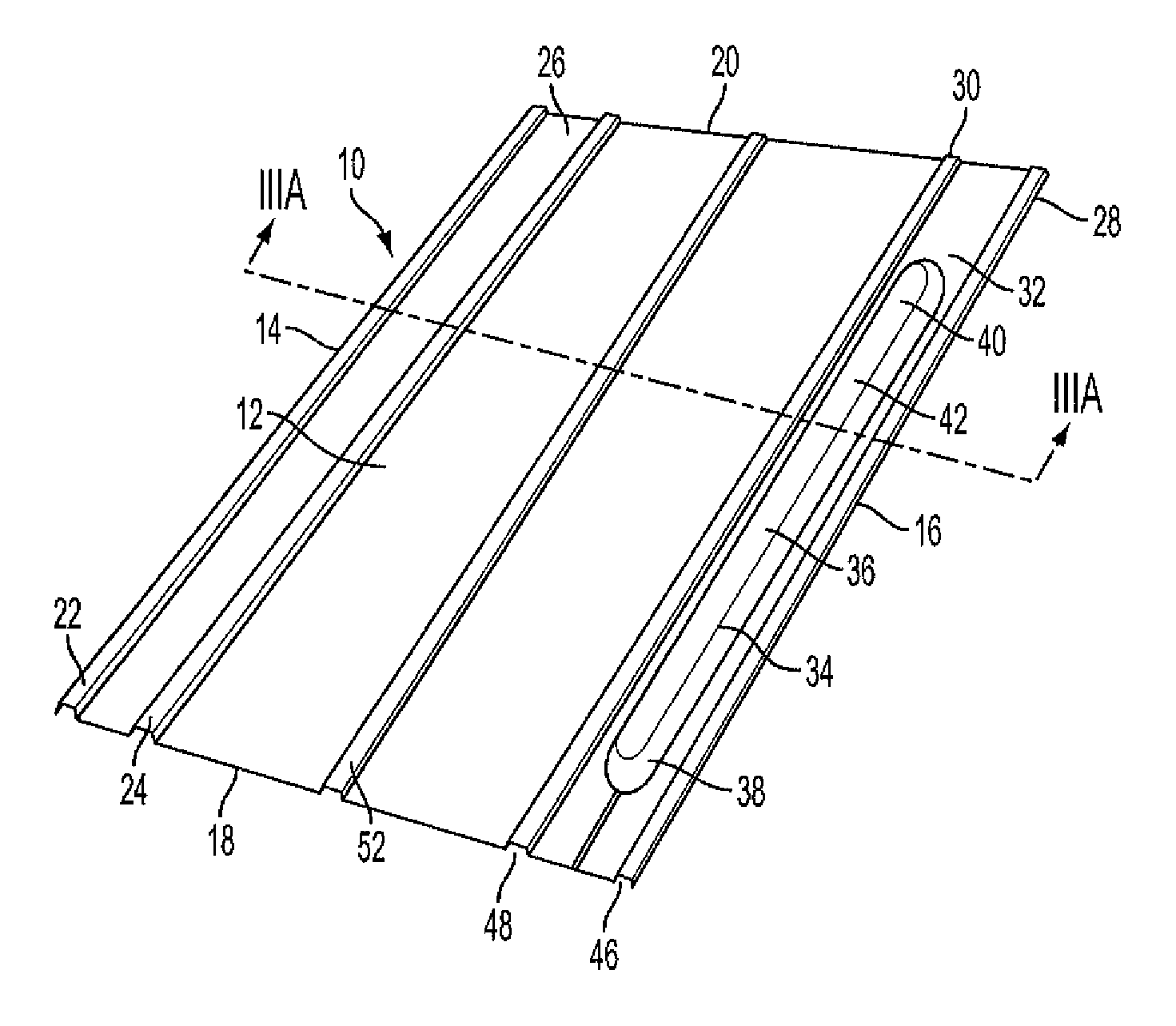
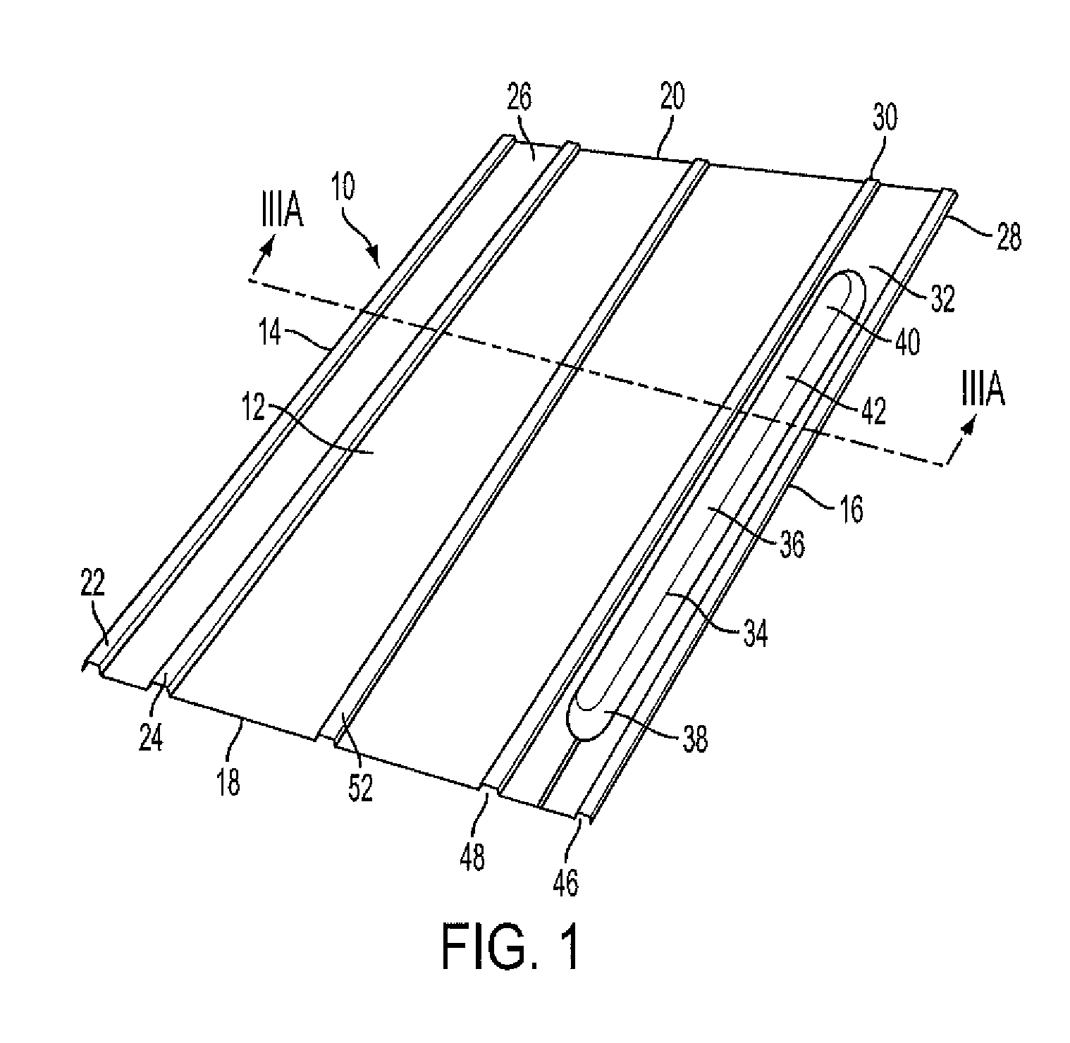
[0059]As particularly shown in FIGS. 1 and 3, disclosed herein is a panel 10 that serves as a roof cover that can be used in combination with conventional roof coverings such as asphalt shingles, tiles, slate and other materials to provide an integrated roof cover that supports an array of PV modules. The PV module array is defined as the organization of PV modules in one of more lateral rows and one or more vertical columns. The PV module array is designed in accordance with the power requirements for the application, the available roof area, the orientation of the roof, requirements of local building codes, and other factors concerning the design of PV module arrays as is known in the art.

[0060]The panel 10 includes a first side 12 that is defined between a first edge 14 and a second edge 16 that are oppositely disposed from each other on panel 10. The first side 12 of panel 10 is also defined between a third edge 18 and a fourth edge 20 that are also oppositely disposed from each...


PUM


Abstract

A panel (10) that is a roof cover for a sloped roof and that also is a mounting system for an array of PV modules (132). The panels (10) define rails (22, 24, 28, 30) that interlock with grooves (46, 48, 124, 126) to secure adjacent panels in each row of the array. The modules (132) are supported by bosses (34, 120) that determine the height of the module array and avoid the interlocking structure between the modules.

Description

BACKGROUND OF THE INVENTION[0001]1. Field of the Invention[0002]The presently disclosed invention relates to rooftop mounting systems for photovoltaic modules and, more particularly, mounting systems that serve as a roof covering.[0003]2. Discussion of the Prior Art[0004]A variety of mounting systems for photovoltaic modules are known in the prior art. In some cases, photovoltaic modules or “PV modules” serve as commercial power stations for generating commercial levels of electric power. In those power station systems, ground-level mountings systems support large numbers of photovoltaic modules that are arranged in a two dimensional array that covers a substantial area, often measured in units of acres. The mounting systems are relatively sophisticated. For example, they often control the orientation of the solar modules in two axes so that the modules track the position of the sun throughout the day in order to more effectively capture the solar energy.[0005]Other, somewhat smalle...

Claims


Application Information

Patent Timeline
Patent Type & Authority Patents(United States)
IPC IPC(8): F24J2/46F24J2/52E04D1/00H01L31/048E04H14/00
CPCH02S20/23F24J2/5228Y02B10/12H01L31/04F24J2/5203Y02E10/47Y02B10/20F24S25/40Y02E10/50Y02B10/10F24S25/30
Inventor SCHICK, MATTHIASTEBBE, HARALDKERMELK, NATHALIEDORMAGEN, MANUELMEREDITH, STEVEN
Owner SUNPOWER CORPORATION
Why Eureka
Try Eureka