Vented upper receiver for a firearm

a technology of upper receiver and firearm, which is applied in the field of firearms, can solve the problems of introducing more problems into the firearm platform, affecting reliability, and not providing an effective or efficient solution for the upper receiver

Active Publication Date: 2014-12-16
HUANG GEORGE +1
View PDF11 Cites 47 Cited by
  • Summary
  • Abstract
  • Description
  • Claims
  • Application Information

AI Technical Summary

Benefits of technology

[0029]The presently disclosed invention separately provides a vented upper receiver that optionally allows a user to control how much exhaust gas is vented from the upper receiver and thereby adjust the amount of back pressure to be directed out of the internal cavity of the upper receiver.
[0030]The presently disclosed invention separately provides a vented forward assist that maintains operability of the forward assist.

Problems solved by technology

Unfortunately, these known attempts to remedy the problem of back pressure building within the cavity of the upper receiver do not provide an effective or efficient solution.
Specialized charging handles only direct the exhaust gases to one side (right side) and can still be problematic if the user is left-handed, because the exhaust gases will be directed into the user's face.
Some of these makeshift solutions can, in fact, introduce more problems into the firearm platform and negatively affect reliability.

Method used


Image

  • Vented upper receiver for a firearm
  • Vented upper receiver for a firearm
  • Vented upper receiver for a firearm

Examples


Embodiment Construction

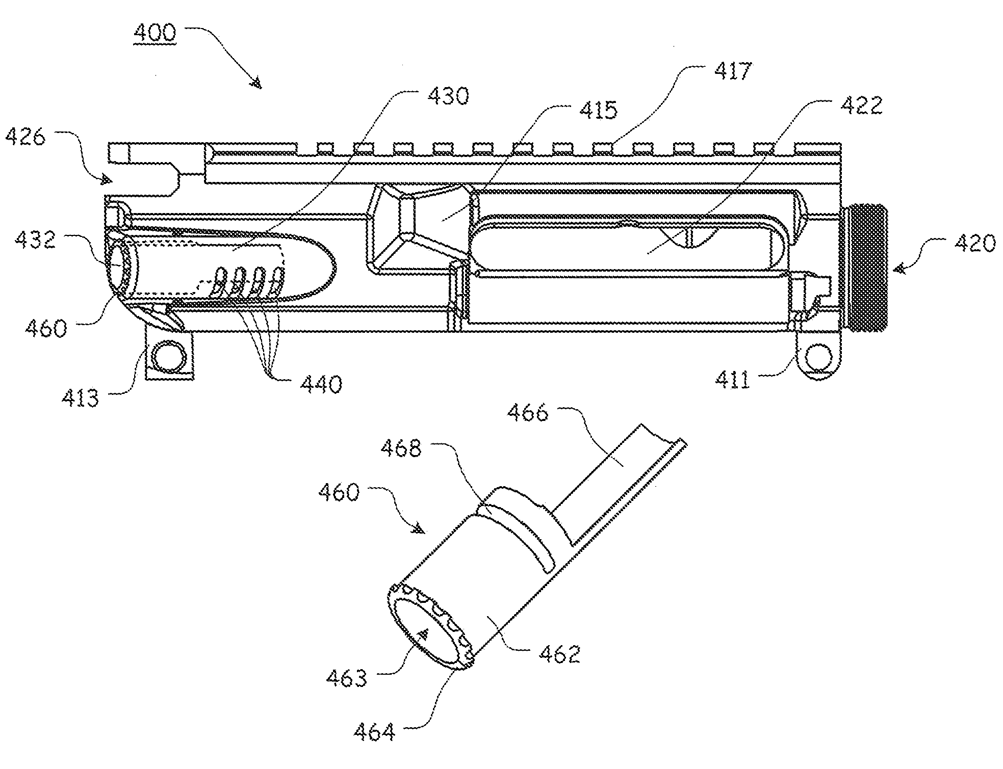
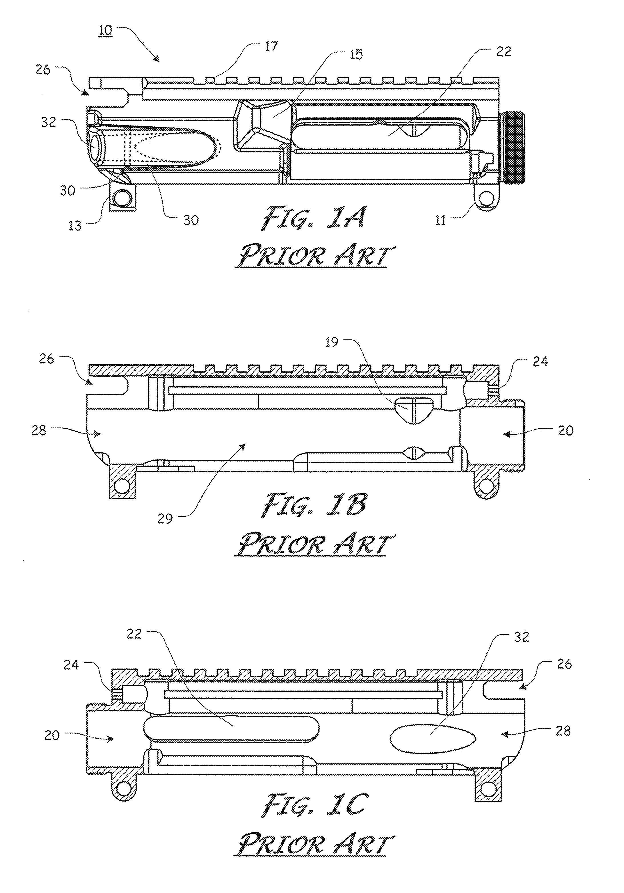
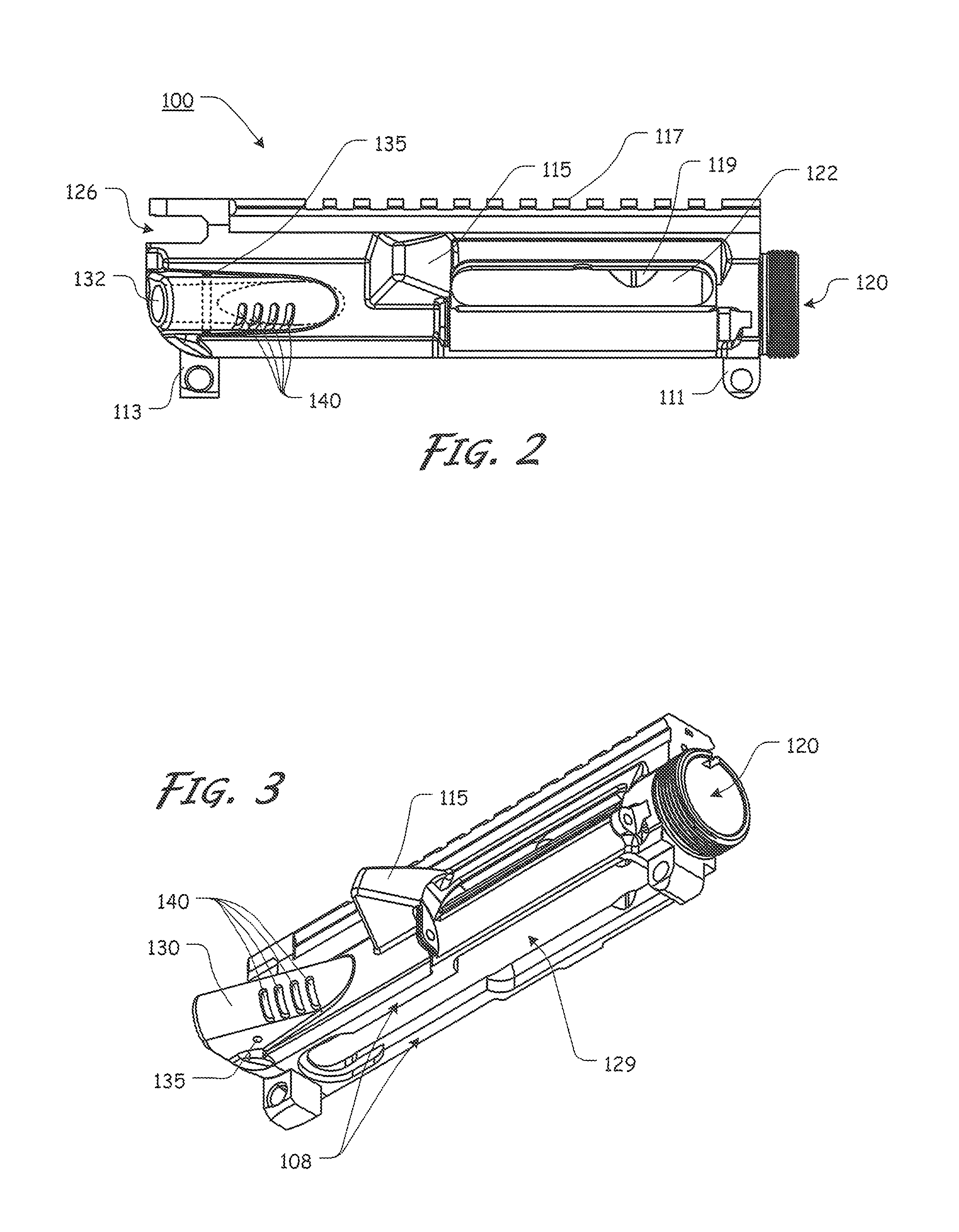
[0070]For simplicity and clarification, the design factors and operating principles of the upper receiver according to this invention are explained with reference to various exemplary embodiments of a vented upper receiver according to this invention. The basic explanation of the design factors and operating principles of the upper receiver is applicable for the understanding, design, and operation of the vented upper receiver of this invention. It should be appreciated that the upper receiver can be adapted to many applications where excessive gas pressure or blowback is experienced within a firearm.

[0071]It should also be appreciated that the terms “AR-15”, “firearm”, and “upper receiver” are used for basic explanation and understanding of the operation of the systems, methods, and apparatuses of this invention. Therefore, the terms “AR-15”, “firearm”, and “upper receiver” are not to be construed as limiting the systems, methods, and apparatuses of this invention. Thus, the terms ...


PUM


Abstract

An pressure reducing component for a firearm that includes one or more vent apertures formed through a side wall or the forward assist cover of an upper receiver. The vent aperture(s) may be completely open to allow gases to be vented from within the upper receiver or may be adjusted to allow a desired amount of gas to be vented from within the upper receiver.

Description

CROSS-REFERENCE TO RELATED APPLICATIONS[0001]Not Applicable.STATEMENT REGARDING FEDERALLY SPONSORED RESEARCH OR DEVELOPMENT[0002]Not Applicable.REFERENCE TO SEQUENCE LISTING, A TABLE, OR A COMPUTER PROGRAM LISTINGCompact Disc Appendix[0003]Not Applicable.NOTICE OF COPYRIGHTED MATERIAL[0004]The disclosure of this patent document contains material that is subject to copyright protection. The copyright owner has no objection to the reproduction by anyone of the patent document or the patent disclosure, as it appears in the Patent and Trademark Office patent file or records, but otherwise reserves all copyright rights whatsoever. Unless otherwise noted, all trademarks and service marks identified herein are owned by the applicant.BACKGROUND OF THE INVENTION[0005]1. Field of the Invention[0006]The present disclosure relates generally to the field of firearms. More specifically, the present invention relates to an upper receiver for a firearm that reduces or eliminates unwanted back press...

Claims


Application Information

Patent Timeline
Patent Type & Authority Patents(United States)
IPC IPC(8): F41A3/00F41C27/00F41A35/00F41A3/66
CPCF41A3/66
Inventor HUANG, GEORGEOGLESBY, PAUL
Owner HUANG GEORGE
Why Eureka
Try Eureka