Touch panel

A touch panel, surface-side technology, applied in the direction of electronic equipment, applications, coatings, etc., can solve the problem that it is difficult to reliably prevent moisture intrusion or dew condensation, and achieve the effect of improving yield and reducing cost

Inactive Publication Date: 2006-03-08
PANASONIC CORP
View PDF2 Cites 10 Cited by
  • Summary
  • Abstract
  • Description
  • Claims
  • Application Information

AI Technical Summary

Problems solved by technology

Its thickness is difficult to reliably prevent moisture intrusion or dew condensation in touch panels made of ITO
[0020] Generally, for the environment using the touch panel, the possibility of rapid and large changes in the environment is less likely to occur in practical applications

Method used


Image

  • Touch panel
  • Touch panel
  • Touch panel

Examples


no. 1 approach

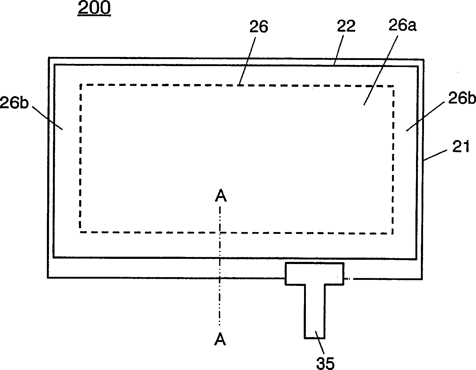
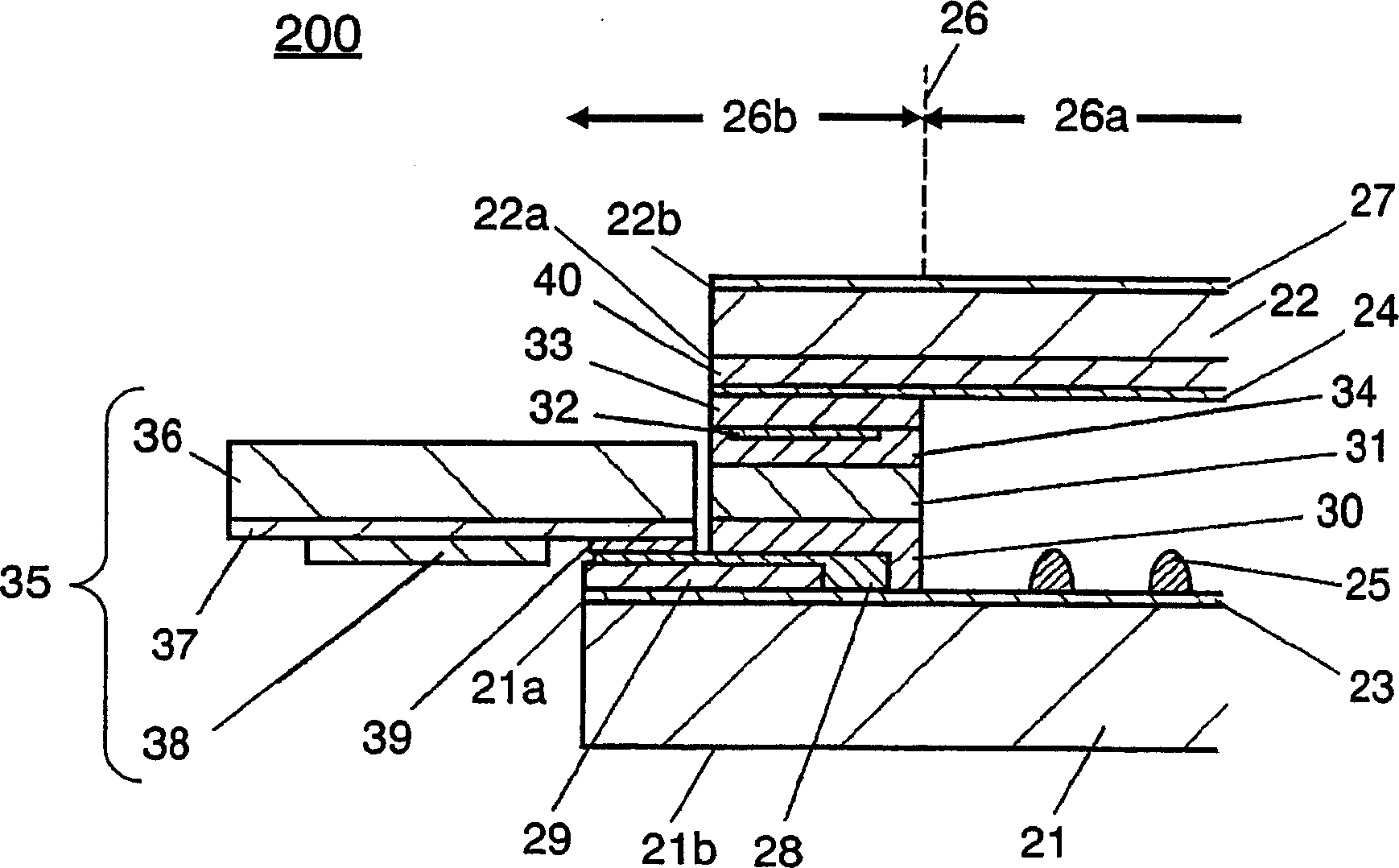
[0044] figure 1 It is a top view of touch panel 200 according to the first embodiment of the present invention. figure 2 Yes figure 1 A cross-sectional view of line A-A is shown.

[0045] The touch panel 200 includes a first transparent substrate 21 , a second transparent substrate 22 , an area boundary portion 26 , a visible area portion 26 a, a non-visible area portion 26 b and a flexible circuit board 35 . The area boundary portion 26 is in contact with the boundary of the visible area portion 26a and the non-visible area portion 26b.

[0046] exist figure 2 Among them, the touch panel 200 includes a first transparent substrate 21 made of soda glass, and a first transparent conductive film 23 made of ITO or the like is formed on the entire surface of one main surface 21a. In addition, micro-sized dot spacers 25 made of insulating epoxy resin are provided on the visible region 26 a on the first transparent conductive film 23 at a predetermined pitch.

[0047] The to...

no. 2 approach

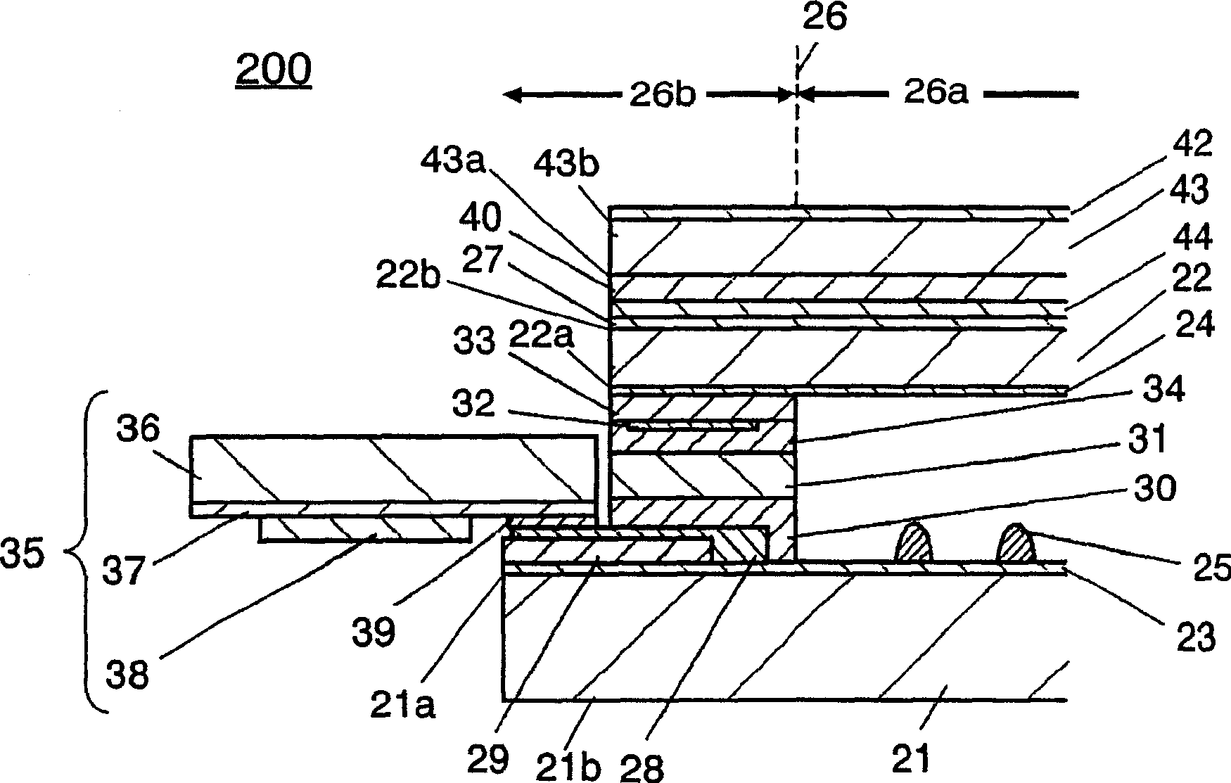
[0080] image 3 It is a cross-sectional view of the touch panel according to the second embodiment of the present invention. Components that are the same as those in the first embodiment are denoted by the same reference numerals, and detailed description thereof will be omitted.

[0081] The touch panel of the second embodiment is the same as the first embodiment in that the water vapor transmission preventing layer 40 is arranged on the second transparent substrate 22 having a polymer thin film structure, but differs in design and the like.

[0082] That is, if image 3 As shown, the second transparent conductive film 24 is formed on one main surface 22a of the second transparent substrate 22 in the second embodiment, and the hard coat layer 27 is formed on the other main surface 22b. On the other hand, the water vapor transmission preventing layer 40 is arranged on a polymer film 43 different from the second transparent substrate 22, and the polymer film 43 is pasted on t...

no. 3 approach

[0092] Figure 4 is a cross-sectional view of a touch panel according to a third embodiment of the present invention. Parts having the same structure as those of the second embodiment are denoted by the same symbols, and detailed description thereof will be omitted.

[0093] The touch panel of the third embodiment is substantially the same as that of the second embodiment in that the water vapor transmission preventing layer 40 is disposed on the other main surface 22b of the second transparent substrate 22 made of a polymer film. The designs are different. like Figure 4 As shown, the second transparent conductive film 24 is provided on one main surface 22a of the second transparent substrate 22, and the hard coat layer 27 is formed on the other main surface 22b, as in the second embodiment.

[0094] Furthermore, in the touch panel of the third embodiment, a glass plate 50 with a thickness of 0.2 mm that functions as the water vapor transmission preventing layer 40 is bond...


PUM

PropertyMeasurementUnit
thicknessaaaaaaaaaa
thicknessaaaaaaaaaa
thicknessaaaaaaaaaa

Abstract

Provided is a dew condensation-free touch panel. Touch panel ( 200 ) has first transparent substrate ( 21 ) and second transparent substrate ( 22 ). First transparent substrate ( 21 ) has main surface ( 21 a) provided with first transparent conductive film ( 23 ). Second transparent substrate ( 22 ) has main surface ( 22 a) on which water vapor transmission preventive layer ( 40 ) as dew condensation prevention part, and second transparent conductive film ( 24 ) are provided in this order. Touch panel ( 200 ) has two regions: visible region ( 26 a) and invisible region ( 26 b) with region boundary ( 26 ) between them. Water vapor transmission preventive layer ( 40 ) is formed at least in visible region ( 26 a). First transparent substrate ( 21 ) and second transparent substrate ( 22 ) are fixedly bonded to each other via adhesive layer ( 31 ) in invisible region ( 26 b) or in the periphery of touch panel ( 200 ) so that first transparent conductive film ( 23 ) and second transparent conductive film ( 24 ) can have a predetermined distance therebetween.

Description

technical field [0001] The present invention relates to a touch panel mounted on the input operation part of various electronic equipment, for example, mounted on the display surface of a liquid crystal display device, etc., corresponding to the display content, and can perform a predetermined signal input operation by pressing with a pen or a finger touch panel. Background technique [0002] In recent years, on portable devices or electronic devices equipped with a menu selection function, touch panels that allow a pen or finger to press a predetermined signal according to the displayed content are increasing. [0003] As such touch panels, several types are known. Next, a resistive film analog type touch panel that is most used will be described with reference to the drawings. However, in order to facilitate understanding of the configuration and structure of the touch panel, the dimensions in the thickness direction are enlarged in the drawings. [0004] Image 6 A cro...

Claims


Application Information

Patent Timeline
Patent Type & Authority Applications(China)
IPC IPC(8): G06F3/033
CPCB32B27/18B32B27/308B32B27/32B32B2307/7242B32B2255/10B32B7/14B32B2307/412B32B2307/408B32B17/1033B32B2457/208G06F3/045B32B17/10018B32B2255/205Y10T428/24942G06F3/041B32B2307/202B32B27/36B32B2307/518B32B27/08B32B2264/102B32B2250/44B32B2457/202B32B2255/26G06F3/04164
Inventor 中西朗村上哲郎藤井树之
Owner PANASONIC CORP
Why Eureka
Try Eureka