
Operation device of straddle type vehicle

a technology of a straddle type and an operation device, which is applied in the direction of mechanical control devices, manual control with a single controlling member, instruments, etc., can solve the problems of limiting the freedom of arrangement, the operation of the controller is difficult, and the inability to operate two or more kinds of functions, etc., to achieve convenient operation, efficient utilization of space, and easy operation

Active Publication Date: 2015-10-01
HONDA MOTOR CO LTD
View PDF9 Cites 8 Cited by
  • Summary
  • Abstract
  • Description
  • Claims
  • Application Information

AI Technical Summary

Benefits of technology

The present invention aims to provide an operation device for a straddle type vehicle that can easily maintain the operation of existing switches, differentiate between them, and operate various functions of the vehicle while keeping a grip.

Problems solved by technology

Hence, to operate the controller provided in the switch box, the finger holding the grip needs to be stretched over the operation ring to operate the controller, and thus operation of the controller is difficult.
This limits freedom in arrangement, as well as requires consideration in operation to sensuously discriminate the rotary controller from other switches.
However, two or more kinds of functions cannot be operated with the technique of the above Patent Document 3.

Method used


Image

  • Operation device of straddle type vehicle
  • Operation device of straddle type vehicle
  • Operation device of straddle type vehicle

Examples


first embodiment

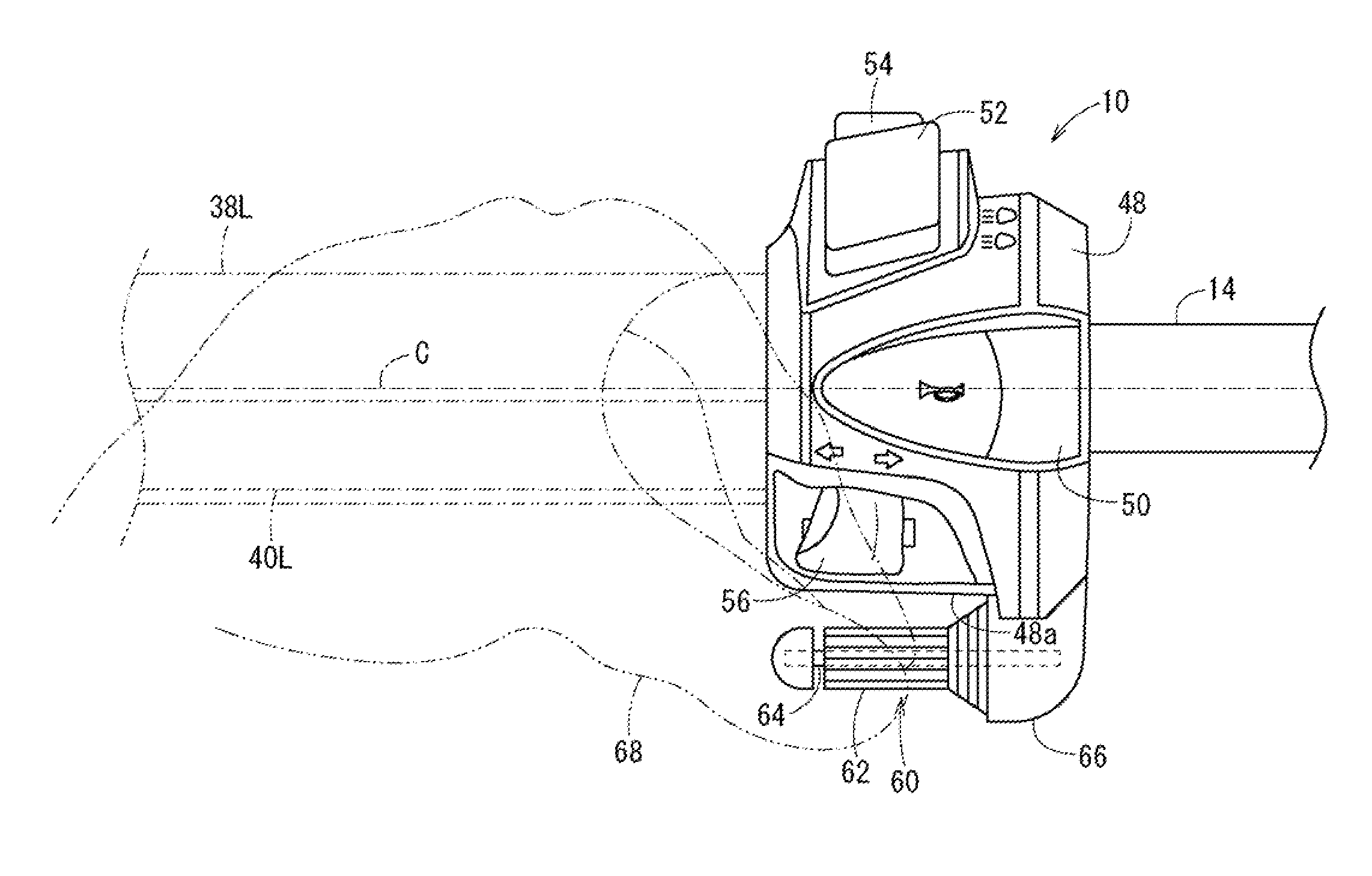
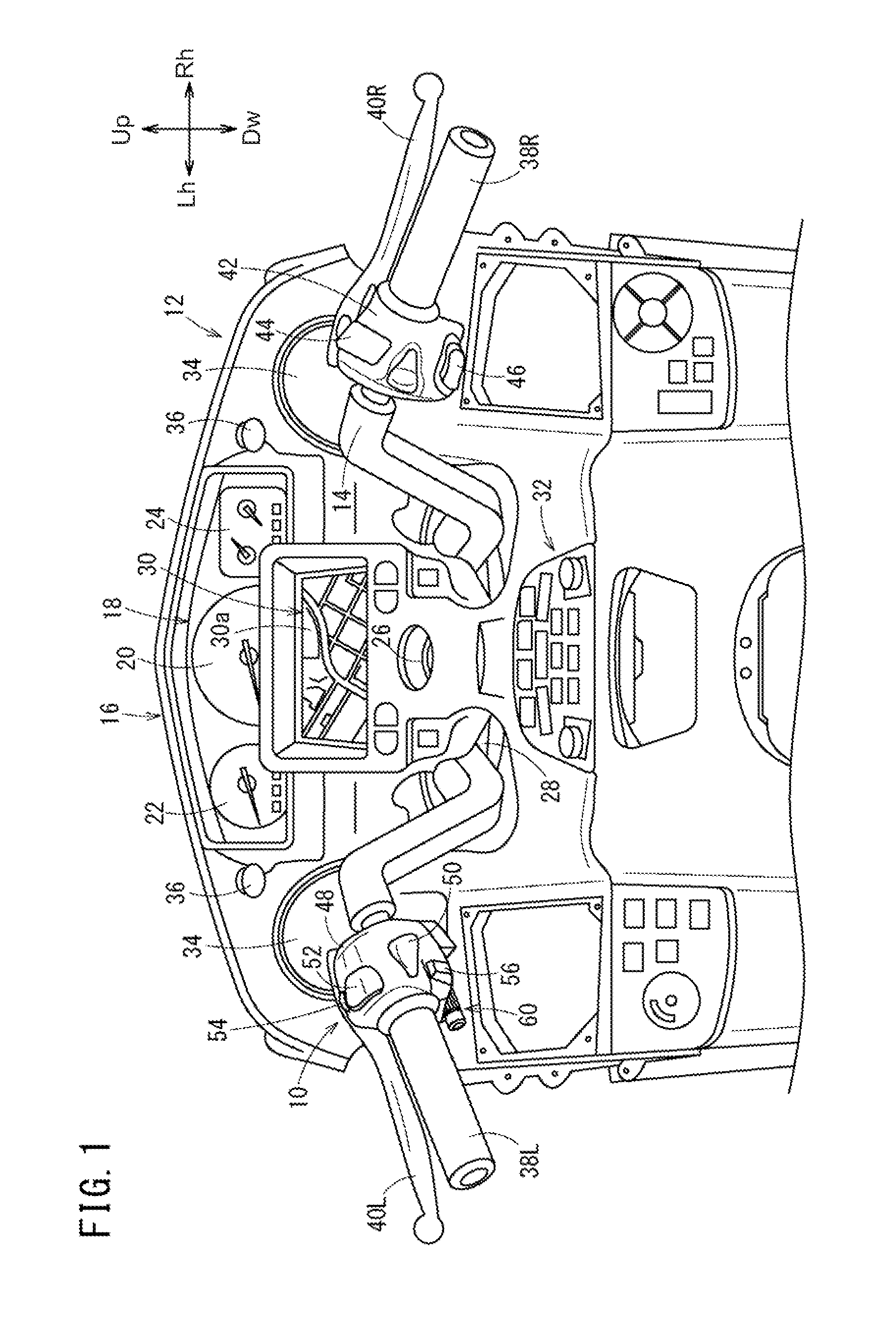
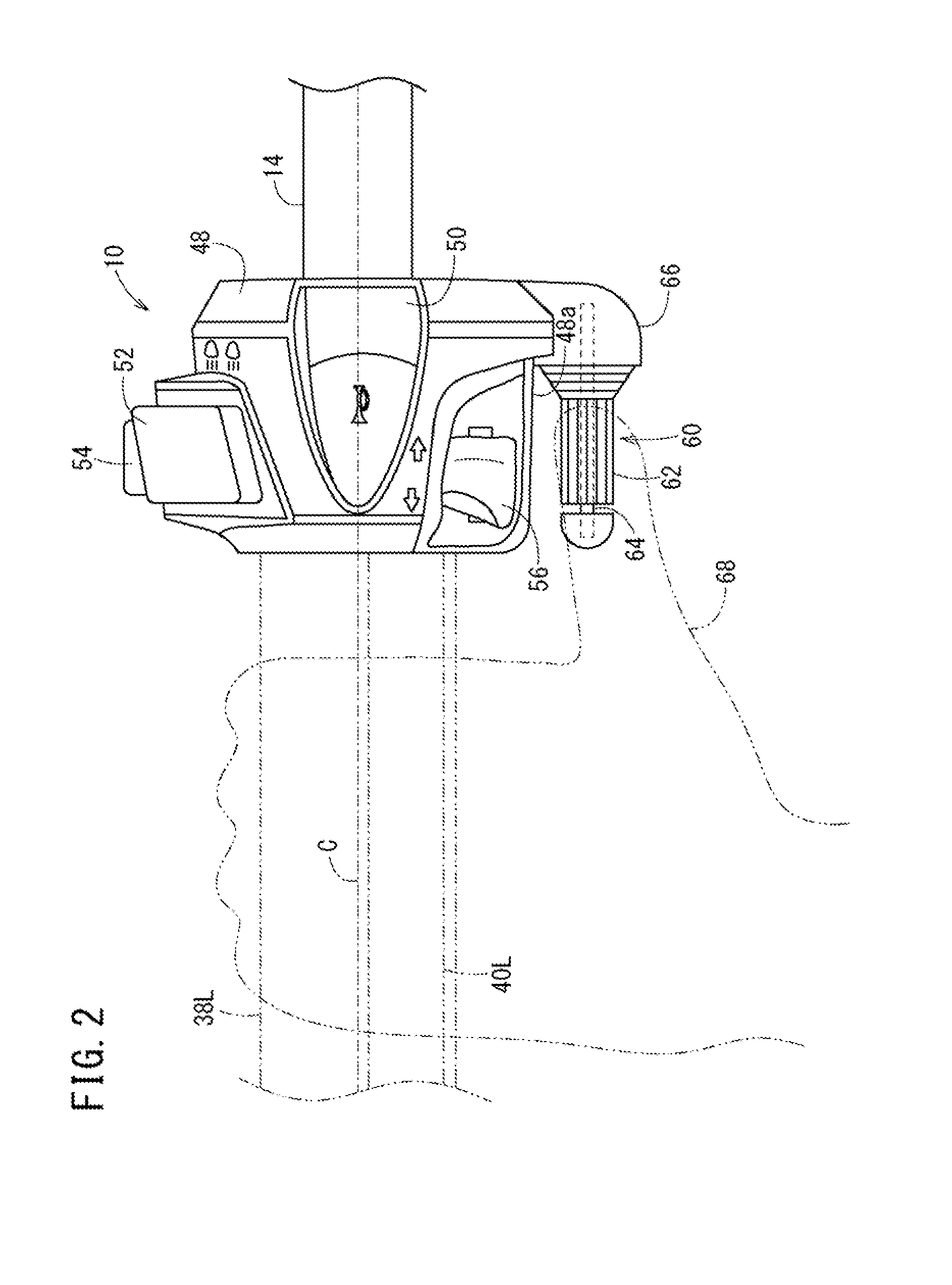
[0062]As has been described, in the first embodiment, the controller operation portion 62 of the controller 60 used to select multiple function menus of equipment, such as the navigation system 30 and the audio unit 32, is arranged in a position different from multiple switches normally used in the straddle type vehicle 12 and provided in the switch box 48. Hence, it is possible to prevent the rider from confusing operation of the multiple switches in the switch box 48 with operation of the controller operation portion 62.

[0063]In addition, the rotary shaft 64 of the controller 60 inside the controller operation portion 62 is arranged lower than the lower wall face 48a of the switch box 48. Accordingly, the controller operation portion 62 is arranged lower than the lower wall face 48a, so that at least two or more kinds of functions (selection and determination of a function menu) can be operated with at least one finger (e.g., the thumb) while keeping hold of the handle grip 38L. A...

third embodiment

[0085]At least a part of a component constituting another electrical switch, which has its controller inside the switch box 48, is arranged in such a manner as to be inserted into the supporting portion 206. In the third embodiment, a component 207 constituting an electrical switch, which has a winker switch 56 inside the switch box 48, is arranged in such a manner as to be inserted into the supporting portion 206.

[0086]The controller 200 has a rotation angle detector 208 for detecting the rotation angle of the controller operation portion 202. The rotation angle detector 208 has a rotation detected body 210 and a rotation angle sensor (electronic component) 212. The rotation detected body 210 is provided in an inner wall of the controller operation portion 202. As shown in FIG. 9, the rotation detected body 210 is a magnetic body configured of an annular ring 210a, and multiple opening portions 210b provided in a penetrating manner along the outer circumferential surface of the rin...


PUM


Abstract

An operation device of a straddle type vehicle has a controller used to operate at least two or more kinds of functions of equipment mounted on the straddle type vehicle. The controller includes a controller operation portion capable of rotary and other freely moving operations. A rotary shaft of the controller inside the controller operation portion is arranged lower than a lower wall face of a switch box.

Description

BACKGROUND[0001]1. Field[0002]The present invention relates to an operation device of a straddle type vehicle used for equipment operation such as operation of audio or a navigation system, switching of a meter display, and switching of traveling modes.[0003]2. Description of the Related Art[0004]As in Patent Document 1 (Published Japanese Translation of PCT International Application No. 2007-530335), a structure is proposed in which a dial-type operation ring rotating around the center axis of a handle bar is attached to a position on the inner side of a grip in the periphery of the handle bar. Normally, in a straddle type vehicle, a switch box including one or multiple controllers operated with the rider's finger is arranged adjacent to an inner end portion of a grip of a handle bar. Accordingly, in the case of the above Patent Document 1, the operation ring having a larger outer diameter than the grip is additionally provided between the inner end portion of the handle grip and t...

Claims


Application Information

Patent Timeline
IPC IPC(8): B62K23/04G05G1/02G05G1/10G05G1/01
CPCB62K23/04G05G1/10G05G1/02G05G1/01B62K11/14B62K23/02G05G9/04792Y10T74/20012H01H25/008
Inventor OSANAI, TAKUYAKIKUCHI, YUTAKAMIKI, MASAHIROICHIKAWA, MANABUTAKEWAKA, TOMOYUKI
Owner HONDA MOTOR CO LTD
Learn More