Self-test for yaw rate sensors

a self-testing and sensor technology, applied in the field of yaw rate sensors, can solve the problem that the section of the quadrature control loop between the feed location and the readout location is not detected by functional testing, and achieve the effect of improving functional testing

Active Publication Date: 2014-12-16
ROBERT BOSCH GMBH
View PDF11 Cites 0 Cited by
  • Summary
  • Abstract
  • Description
  • Claims
  • Application Information

AI Technical Summary

Benefits of technology

[0005]An object of the present invention is to provide improved functional testing. The object is achieved using the yaw rate sensor, and using the method. This advantage is achieved in that a readout location for a response signal in relation to a processing direction of the test signal is situated between a feed location for a test signal and an actuator for feeding back a deflection of the movable mass structure.
[0006]In another specific embodiment, for applying the test signal to the movable mass structure different actuators, in particular different electrodes, are provided than for a quadrature compensation. The complexity is reduced in this way.
[0007]In another design, a test signal is used which results in a response signal which is essentially mean-value-free. Offset errors may be avoided in this way.

Problems solved by technology

In the conventional sensor it is disadvantageous that a section of the quadrature control loop between the feed location and the readout location is not detected by the functional testing.

Method used


Image

  • Self-test for yaw rate sensors
  • Self-test for yaw rate sensors
  • Self-test for yaw rate sensors

Examples


Embodiment Construction

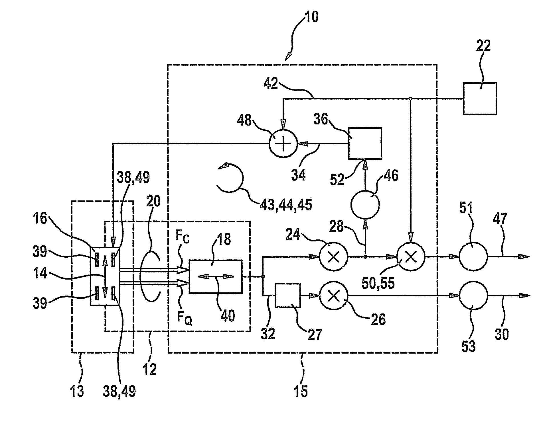
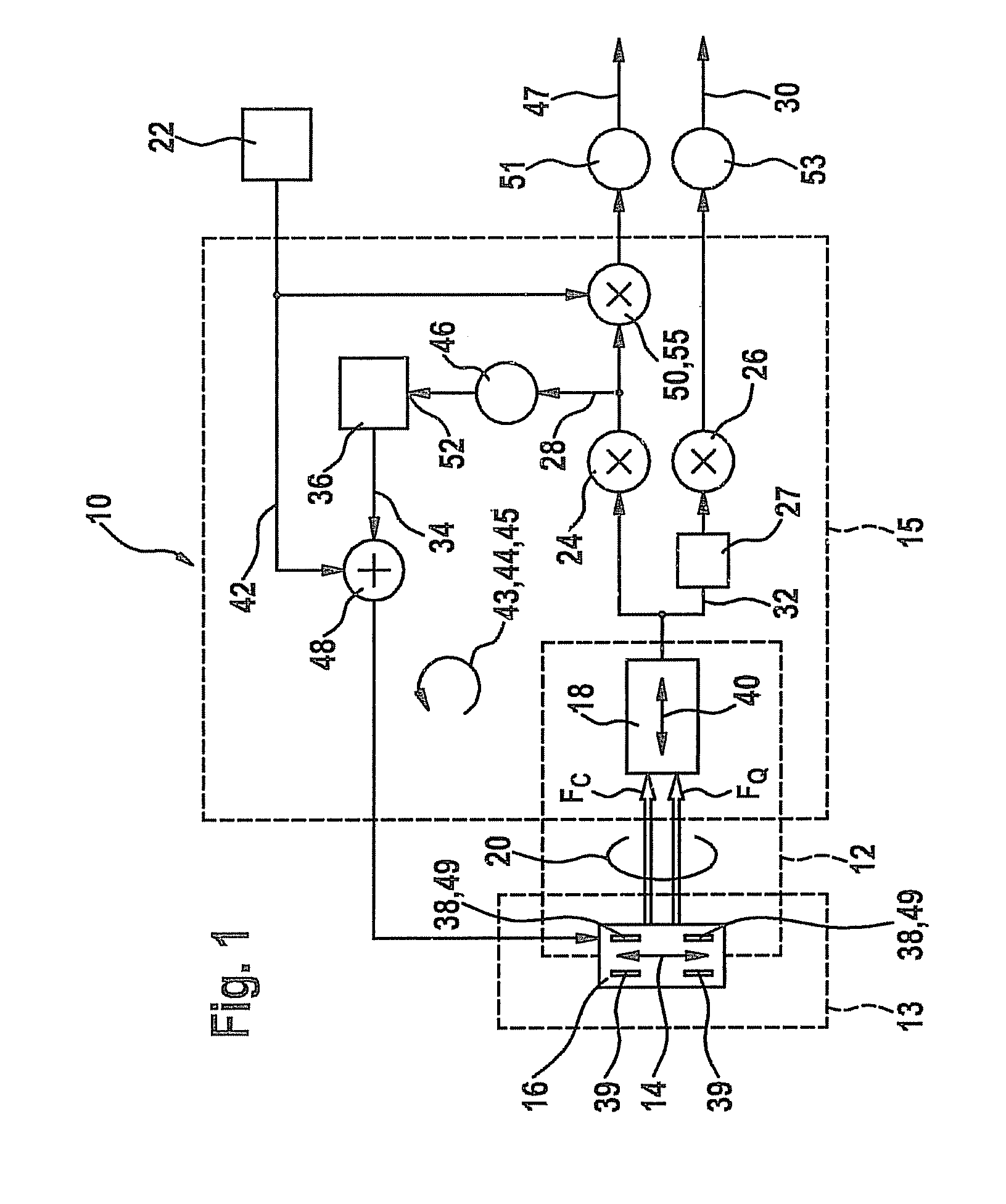
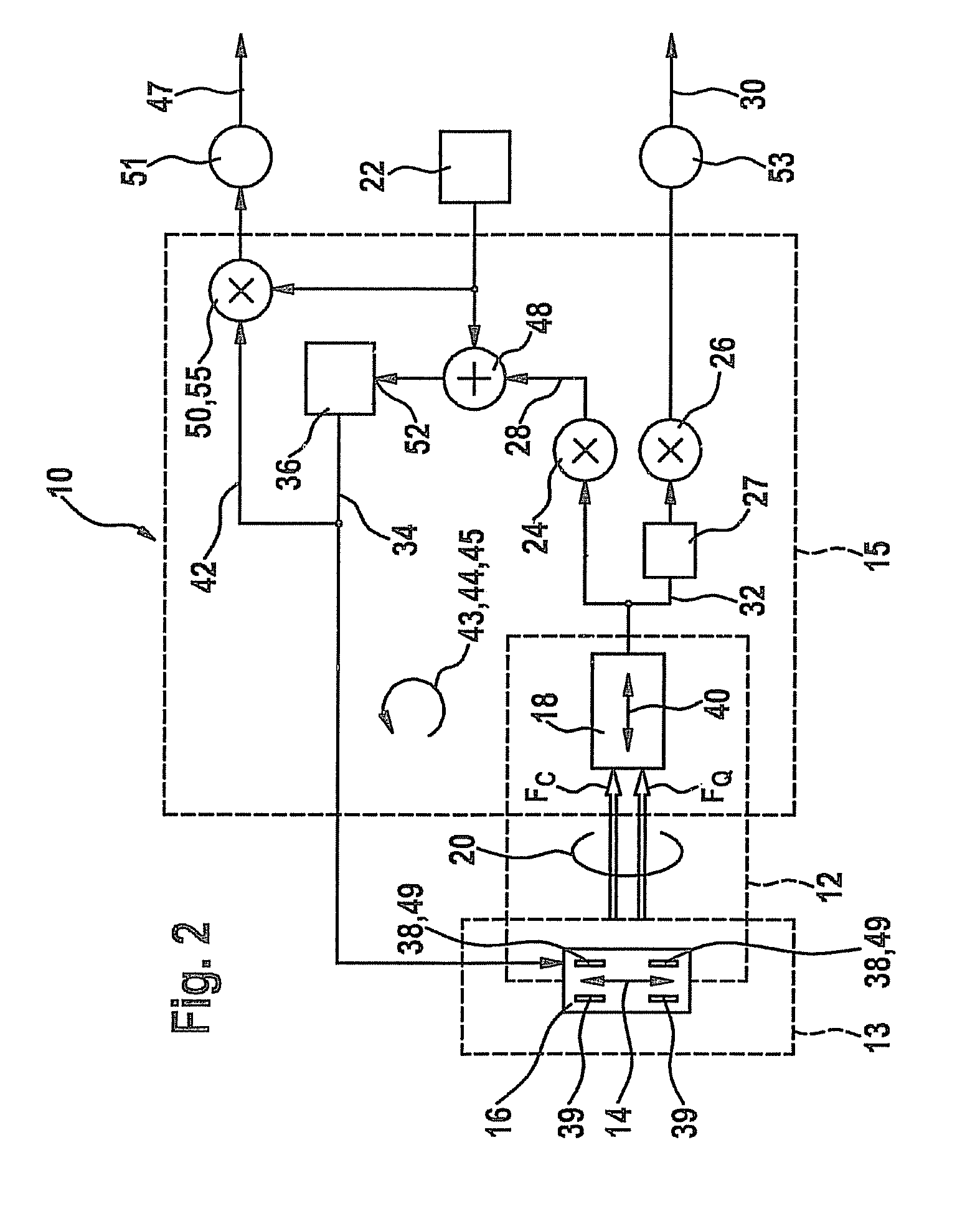
[0017]In a micromechanical yaw rate sensor 10 (vibration gyrometer), use is made of the Coriolis effect for determining an external yaw rate Ω. For this purpose, a movable mass structure 12 of sensor 10 is set in motion at a speed v in a first direction x. This is achieved with the aid of a drive vibration 14 having a frequency ωA. Movable mass structure 12 may include a drive mass 16 and a detection mass 18, a preferred vibration direction x of drive mass 16 being oriented orthogonally relative to a preferred vibration direction y of detection mass 18. As the result of mechanical coupling 20 with the aid of a spring system, a Coriolis force FC which results from a yaw rate Ω of mass structure 12 and which acts on drive mass 16 is transmitted to detection mass 18 in the direction of preferred vibration direction y of detection mass 18. Since in general the two vibration directions x, y are not precisely orthogonal, deflection 14 of drive mass 16 results in a second force component F...


PUM


Abstract

A yaw rate sensor (10) includes a movable mass structure (12) and a drive component (13) which is suitable for setting the movable mass structure (12) in motion (14), and an analysis component (15) which is suitable for detecting a response (40) of the movable mass structure (12) to a yaw rate (Ω). A method for functional testing of a yaw rate sensor (10) includes the following steps: driving a movable mass structure (12), feeding a test signal (42) into a quadrature control loop (44) at a feed point (48) of the quadrature control loop (44), feeding back a deflection (40) of the movable mass structure (12), detecting a measure of the feedback of the movable mass structure (12), and reading out the response signal (47) from the quadrature control loop (44). In the yaw rate sensor (10) and also in the method, the readout of the response signal (47) in relation to a processing direction (45) of the test signal (42) is provided between a feed point (48) for a test signal (42) and an actuator (38) for feeding back a deflection (40) of the movable mass structure (12).

Description

BACKGROUND OF THE INVENTION[0001]1. Field of the Invention[0002]The present invention relates to multiple yaw rate sensors, each yaw rate sensor including a movable mass structure, a drive component, and an analysis component, the drive component being suitable for setting and / or keeping the movable mass structure in motion, and the analysis component being suitable for detecting a response of the movable mass structure to a yaw rate. Moreover, the present invention relates to multiple methods for functional testing of a yaw rate sensor, each method including the following steps: driving a movable mass structure, feeding a test signal into a quadrature control loop at a feed location of the quadrature control loop, feeding back a deflection of the movable mass structure, detecting a measure of the feedback of the movable mass structure, and reading out a response signal from the quadrature control loop.[0003]2. Description of Related Art[0004]In a conventional sensor, such as that d...

Claims


Application Information

Patent Timeline
Patent Type & Authority Patents(United States)
IPC IPC(8): G01C19/5726G01C19/00
CPCG01C19/5726G01C25/00G01C19/56
Inventor BAUER, WOLFRAMCLASSEN, JOHANNESWILLIG, RAINERMEIER, MATTHIASKUHLMANN, BURKHARDREIMANN, MATHIASESCH, ERMINSCHWARZ, HANS-DIETERVEITH, MICHAELLANG, CHRISTOPHGOMEZ, UDO-MARTIN
Owner ROBERT BOSCH GMBH
Why Eureka
Try Eureka