Centrifugal-pendulum vibration absorbing device

a centrifugal pendulum and vibration absorbing technology, which is applied in the direction of shock absorbers, fluid gearings, gearing, etc., can solve the problems of abnormal sound, increase the size of the mass body, and reduce the clearance between the mass body and the adjacent, so as to improve the vibration absorbing performance of the centrifugal pendulum vibration absorbing device, the effect of improving the vibration absorbing performance and the same structur

Inactive Publication Date: 2014-12-16
AISIN AW CO LTD
View PDF26 Cites 12 Cited by
  • Summary
  • Abstract
  • Description
  • Claims
  • Application Information

AI Technical Summary

Benefits of technology

[0006]The centrifugal-pendulum vibration absorbing devices discussed above can damp vibration transmitted to the support member more effectively as the weight of each mass body is larger. However, increasing the weight of each mass body of the centrifugal-pendulum vibration absorbing device basically inevitably increases the size of the mass bodies, and the increased size of the mass bodies reduces the clearance between mass bodies disposed adjacent to each other. Therefore, in the case where the size of the mass bodies is increased to secure the weight, mass bodies disposed adjacent to each other may come so close to each other that respective end portions of the mass bodies collide against each other to cause occurrence of an abnormal sound when the rotational speed of the support member is relatively low and the behavior of the mass bodies tends to be unstable, for example.
[0007]It is therefore a main object of the present invention to provide a centrifugal-pendulum vibration absorbing device that can secure the weight of mass bodies while suppressing a collision between mass bodies disposed adjacent to each other and occurrence of an abnormal sound due to such a collision.

Problems solved by technology

However, increasing the weight of each mass body of the centrifugal-pendulum vibration absorbing device basically inevitably increases the size of the mass bodies, and the increased size of the mass bodies reduces the clearance between mass bodies disposed adjacent to each other.
Therefore, in the case where the size of the mass bodies is increased to secure the weight, mass bodies disposed adjacent to each other may come so close to each other that respective end portions of the mass bodies collide against each other to cause occurrence of an abnormal sound when the rotational speed of the support member is relatively low and the behavior of the mass bodies tends to be unstable, for example.

Method used


Image

  • Centrifugal-pendulum vibration absorbing device
  • Centrifugal-pendulum vibration absorbing device
  • Centrifugal-pendulum vibration absorbing device

Examples


Embodiment Construction

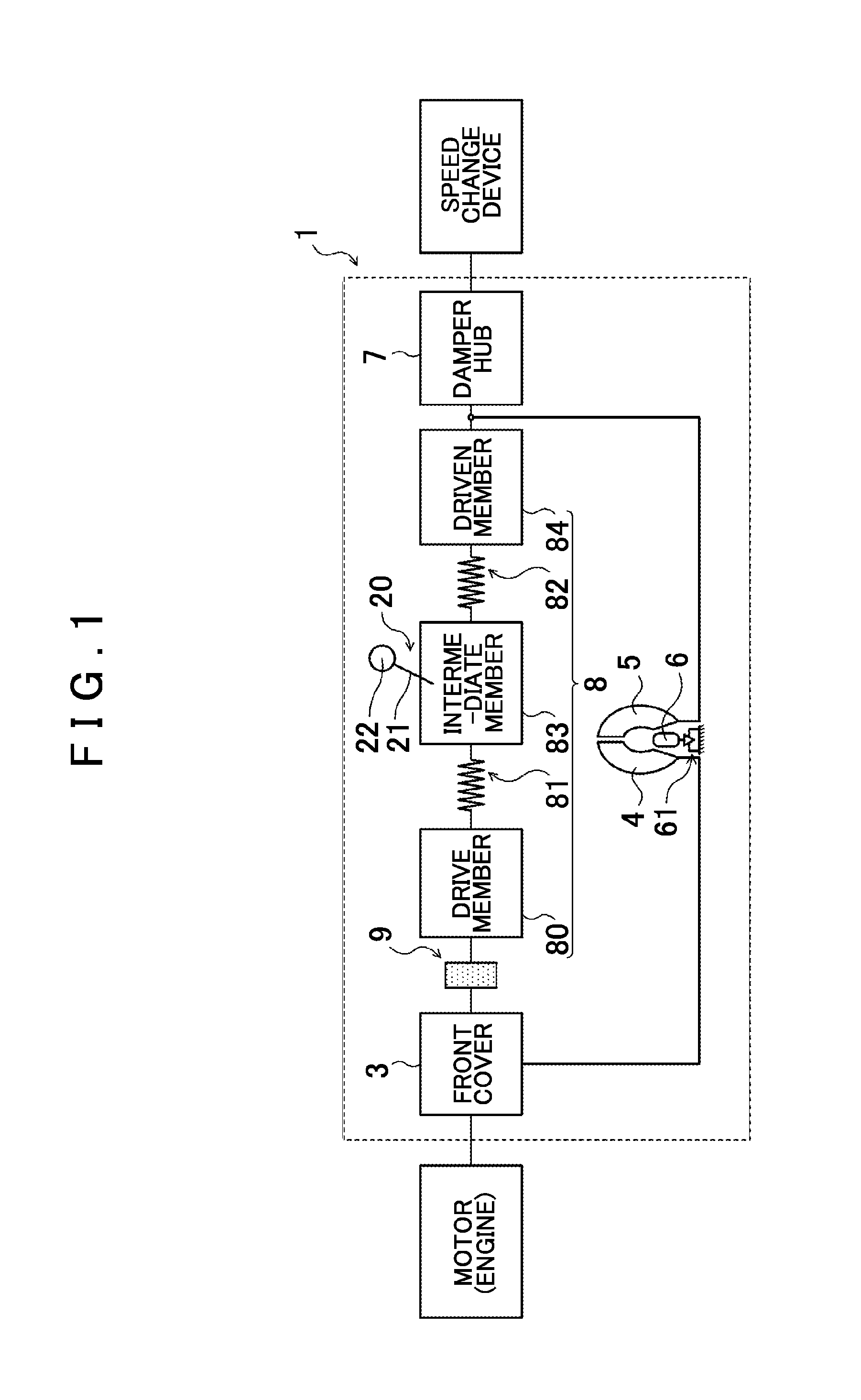
[0037]Now, an embodiment of the present invention will be described.

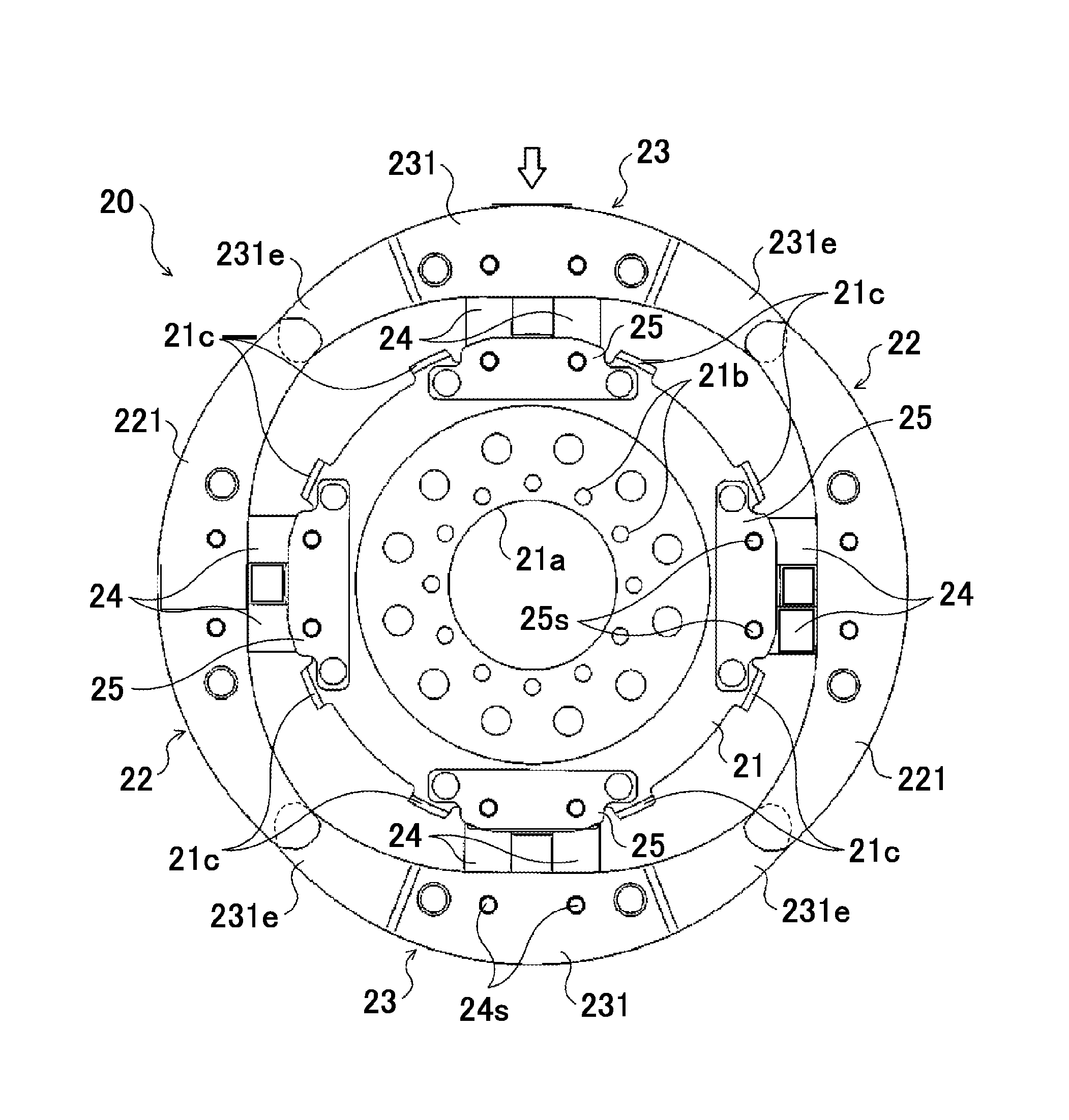
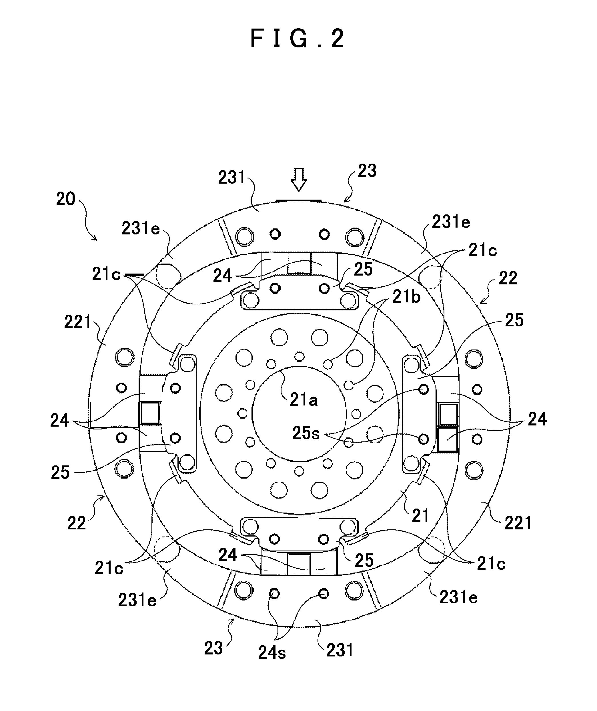
[0038]FIG. 1 shows a schematic configuration of a fluid transmission device 1 including a centrifugal-pendulum vibration absorbing device 20 according to an embodiment of the present invention. The fluid transmission device 1 shown in FIG. 1 is a torque converter mounted as a starting device on a vehicle including an engine (internal combustion engine) serving as a motor, and includes a front cover (input member) 3 coupled to a crankshaft (not shown) of the engine, a pump impeller (input-side fluid transmission element) 4 fixed to the front cover 3, a turbine runner (output-side fluid transmission element) 5 disposed coaxially with the pump impeller 4 so as to be rotatable, a stator 6 that rectifies a flow of working oil (working fluid) from the turbine runner 5 to the pump impeller 4, a damper hub (output member) 7 fixed to an input shaft of a speed change device which is an automatic transmission (AT) or a continu...


PUM


Abstract

A centrifugal-pendulum vibration absorbing device, including a member attached coaxially with a rotary element; and mass bodies swingably coupled to the support member and disposed adjacent to each other in a circumferential direction. The mass bodies are configured such that when a first mass body, which is one of two mass bodies disposed adjacent to each other, and a second mass body, which is the other of the two mass bodies, move with respect to the support member so as to approach each other, the first mass body and the second mass body overlap each other as seen from an axial direction of the rotary element.

Description

[0001]The disclosure of Japanese Patent Applications No. 2010-294401 filed on Dec. 29, 2010 and No. 2010-294404 filed on Dec. 29, 2010 including the specification, drawings and abstract is incorporated herein by reference in its entirety.BACKGROUND OF THE INVENTION[0002]1. Field of the Invention[0003]The present invention relates to a centrifugal-pendulum vibration absorbing device including a support member attached coaxially with a rotary element and a plurality of mass bodies swingably coupled to the support member and disposed adjacent to each other in the circumferential direction.[0004]2. Description of the Related Art[0005]Hitherto, there has been known a centrifugal-pendulum vibration absorbing device including a support member attached coaxially with a turbine runner of a fluid transmission device and a plurality of pendulum masses (mass bodies) each coupled to the support member via a support roller so as to be swingable with respect to the support member (see German Paten...

Claims


Application Information

Patent Timeline
Patent Type & Authority Patents(United States)
IPC IPC(8): F16H45/02F16F7/10F16F15/14
CPCF16H2045/0263F16H45/02F16F15/145Y10T74/2128Y10T464/50F16F15/10
Inventor TAKIKAWA, YOSHIHIROMARUYAMA, KAZUTOITOU, KAZUHIROMAEDA, KOJI
Owner AISIN AW CO LTD
Why Eureka
Try Eureka