Printer architecture enabling narrow or wide front facing orientation

a printing machine and front facing technology, applied in electrographic processes, instruments, transportation and packaging, etc., can solve the problems of large projected footprint that is not ideal for stated orientation considerations, e-w printer configuration, and insufficient desk or space efficiency in most applications, so as to achieve greater flexibility for customers

Inactive Publication Date: 2014-12-16
XEROX CORP
View PDF3 Cites 1 Cited by
  • Summary
  • Abstract
  • Description
  • Claims
  • Application Information

AI Technical Summary

Benefits of technology

[0007]Printing products have not been produced with a basic engine that can be configured for either left-right or front-back placement orientation to best accommodate customer preferences. The present disclosure sets forth a printer architecture that enables a printer with a rectangular foot print to be configured with media input and operator controls oriented at either the narrow end or wide side, that surface becoming the “front” of the unit. Controls and / or display(s) are mounted such that either the end or side orientation can be accommodated. The media input tray is a separate assembly so that selection of the tray with access to end or side complements the user control panel in establishing the front of the machine. This disclosure includes the combination of control / display mounting and oriented media tray structure integration with the print engine to establish which of the printer surfaces is considered the front, allowing for multiple orientations of the printer and greater flexibility to the customer.
[0009]The interface unit can include a display and / or a user input device. The housing can include a top side adjacent the first and second sides, and the interface port can be located on the top side of the housing. The interface port can be located in a corner of the top side adjacent the first and second sides. Alternately, the interface unit may be coupled to an interface port of the media processing unit (any imaging device, all forms hereby encompassed by the term printer) located at any portion of the printer capable of providing the desirable orientation flexibility of the present concept. The interface port can further comprise a communication interface for linking a central processing unit of the paper processing device with the interface unit. In one configuration, the device can further comprise a media input tray having an elongate footprint and a media drawer opening to a narrow side of the media input tray for use with the interface unit in the first position. In another configuration, the device can further comprise a media input tray having an elongate footprint and a media drawer opening to a wide side of the media input tray for use with the interface unit in the second position. A media size sensor can be supported by the housing, the media size sensor adapted to sense a media size of media supported in a media tray attached to the housing.

Problems solved by technology

This results in a large projected footprint that is not ideal for stated orientation considerations.
The E-W printer configuration puts the wide side at the front and is not desk or space efficient in most applications.
It has been found that transitioning the print engine design and resultant models from a N-S to E-W configuration has become desirable to emphasize MFP sales, but the orientation requirement is a compromise that has a negative effect on some customers, significantly, those that place a printer on a work station desk where width is limited.
A drawback, however, is this new printer architecture generally forces an orientation that is incompatible with the narrow front many customers prefer, or are forced into for placement efficiency, on desks or limited space tables.

Method used


Image

  • Printer architecture enabling narrow or wide front facing orientation
  • Printer architecture enabling narrow or wide front facing orientation
  • Printer architecture enabling narrow or wide front facing orientation

Examples


Embodiment Construction

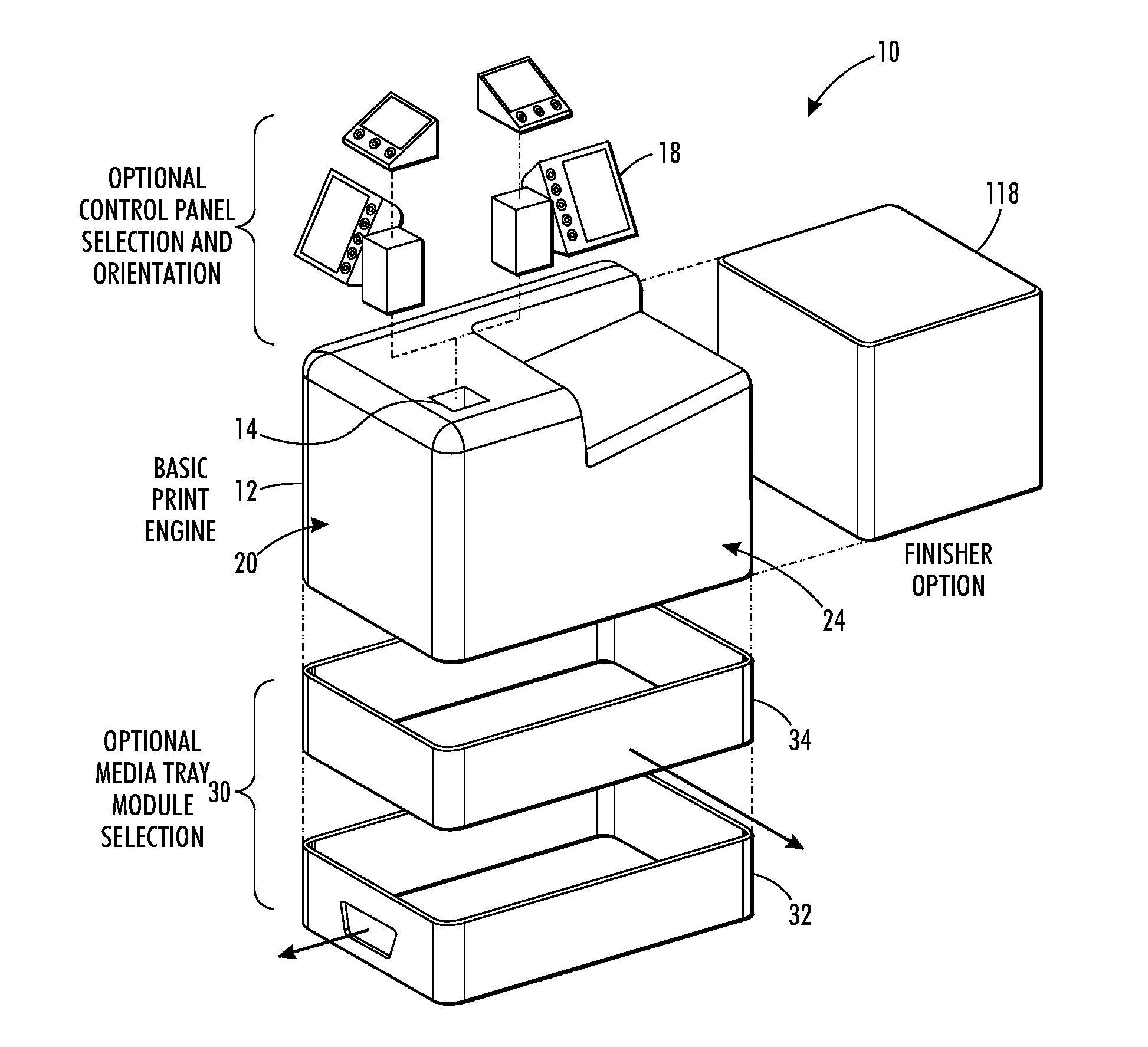
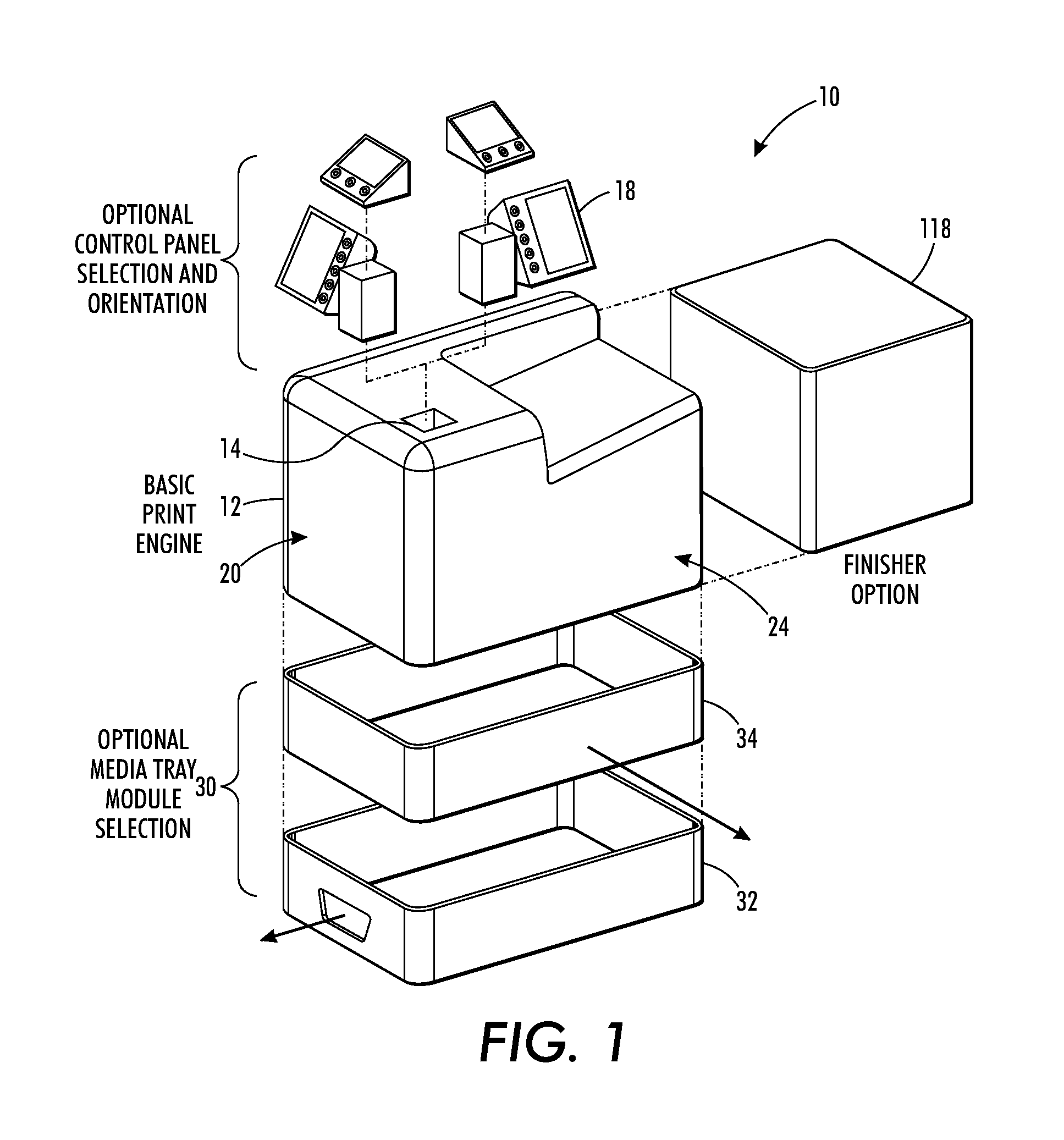
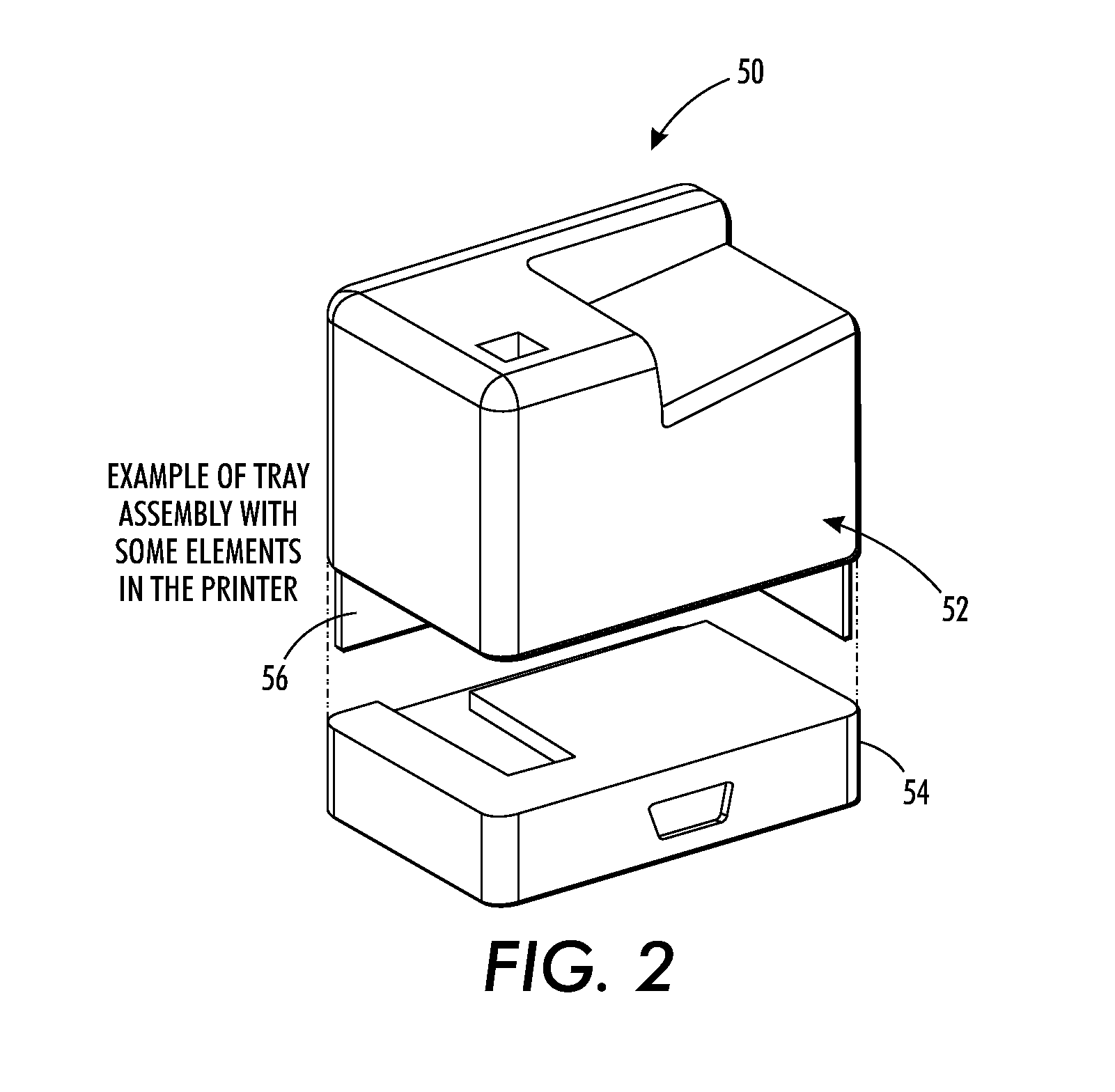
[0019]The present disclosure sets forth a module printer wherein the printer can be configured to address user orientation preference or requirements by attaching or positioning primary subsystems, such as the user control panel, for example, a touch screen display, etc., to the surface desired as the front of the device. A control panel can be minimalist, as simple as a few buttons and small text display. The trend is to more friendly and functional control interfaces such as larger touch screens which may be used alone or in combination with physical buttons. The present concept accommodates desired configurations by allowing different panels to be used, as appropriate to the feature set and price point of the end product. Media input tray assemblies can then be selected to face the front of the device. Orientation of media input access, such as with a slide out paper tray, is defined by the tray housing structure and the direction of tray insertion and withdrawal from either a na...


PUM

PropertyMeasurementUnit
sizeaaaaaaaaaa
aspect ratioaaaaaaaaaa
flexibleaaaaaaaaaa

Abstract

A printer architecture that enables a printer (or other media processing device) with an elongate foot print to be configured with media input and operator controls oriented at either a narrow end or a wide side thereof, that surface becoming the “front” of the unit. Controls and / or display(s) are mounted such that either the end or side orientation can be accommodated. The media input tray includes a separate assembly so that selection of the tray with access to end or side complements the user control panel in establishing the front of the machine. The combination of control / display mounting and oriented media tray structure integration with the print engine to establish which of the printer surfaces is considered the front allows for multiple orientations of the printer and greater flexibility to the customer.

Description

BACKGROUND[0001]Printers and related products, such as MFP's, have an architecture that defines the placement orientation of the unit relative to user access. For example, generally a printer is configured such that the most significant interactions, such as operation or setting selection via control panel or display and adding media to the input tray, faces what would be considered the front of the unit. Printers do not typically have a square footprint so the placement orientation, driven by primary user interfaces, determines which of the narrow or wide surfaces is the unit front. The aspect ratio is often an outcome of the paper path, its direction generally along the long axis. A narrow front with the paper path front to back, is often preferred for desks and limited table space. The wider orientation with a left-right paper path, is more flexible for auto document scanners and when equipping the unit with optional finishers (including, for example, sorting devices, collating d...

Claims


Application Information

Patent Timeline
Patent Type & Authority Patents(United States)
IPC IPC(8): B65H3/44
CPCG03G21/1609B41J11/003Y10T29/49826
Inventor WALSH, MARTIN SCOTTCRAWFORD, TIMOTHYTENNANT, MARK H.BOYCE, AARON L.BURRESS, EDWARD F.FRAZIER, ISAAC S.FANNING, JOHN E.JONES, BRENT R.SMITH, TODD D.SNYDER, TREVOR J.URBAN, CARL T.VAN GASSE, PAULWOODWARD, PAUL
Owner XEROX CORP
Why Eureka
Try Eureka