Multi-function cart

a multi-functional, cart technology, applied in the direction of carriage/perambulator with multiple axes, child seats, cycle equipment, etc., can solve the problems of insufficient supplies within close proximity of disasters, inability of emergency responders to reach many victims, and inability to treat each victim. convenient and clean

Active Publication Date: 2014-12-16
BENGTZEN TROY
View PDF35 Cites 13 Cited by
  • Summary
  • Abstract
  • Description
  • Claims
  • Application Information

AI Technical Summary

Benefits of technology

[0004]The present invention is directed to a multi-function cart for storing and transporting emergency, camping, recreational, or other supplies. The multi-function cart serves initially as a mobile storage container having a compact design that allows the storage container to be stored in many different locations including inside or outside the home, business, institution, church, or other buildings, and above or below ground such as on a deck or patio, in a shed, garage, or basement, etc. where it can be quickly accessed in case of an emergency or simply for convenience sake. The convenience and cleanliness provided by this product is a key benefit of this device.
[0005]The multi-function cart is convertible from the mobile storage container into various devices that provide functionality to sustain life during or after a disaster, and to clean-up and rebuild after a disaster has occurred. In this manner, the multi-function cart enables victims to maintain a semblance of normalcy and to quickly care for themselves, their families, classmates, coworkers, or neighbors in the event of an emergency, and further encourages victims to immediately begin the clean-up and rebuilding process after the emergency.
[0010]Each pair of hub brackets is aligned on the corresponding side of the shell so that one or more tubes can be stored along the surface of the shell by inserting each tube through a corresponding hole in each hub bracket of the pair of hub brackets, and so that the first shell can be secured to the second shell when the second shell is aligned with the first shell by connecting each hub bracket on the first shell to an opposing hub bracket on the second shell. In certain embodiments, a support bar extends between each pair of support brackets on the same side of the shell to act as an exterior frame member to make the sides of the shell more rigid and strong.
[0015]In some embodiments, each of the hub brackets is positioned on the sides of the shell so that an opening formed in the lip aligns with the hub bracket such that any of the interchangeable tubes can be inserted into the opening and engage with the hub bracket to form a handle for the shell. Alternatively, a portion of the hub bracket may extend through the opening such that the interchangeable tubes first engage with the hub bracket and continue such engagement as they are inserted into the openings. Additionally, the positioning of the hub brackets permits the first shell to be secured to the second shell when the second shell is aligned with the first shell by connecting a top adapter of each hub bracket on the first shell to an opposing top adapter on a hub bracket of the second shell using a clamping or securing device that draws the respective hub brackets of the two shells together and permits a variable force to be exerted between the hub brackets, as needed. Thus, the clamping or securing device may be adjusted as necessary to maintain a seal between the two shells.

Problems solved by technology

When a disaster occurs, whether natural or man-made, the injury and death toll often depends on how quickly emergency supplies can be delivered to the victims of the disaster.
These emergency responders, in some cases, may not be able to reach many victims in a timely fashion such as when the disaster is of great magnitude or widely spread.
For example, if a large number of people are in need of emergency supplies, the supplies available within close proximity of a disaster may not be adequate to treat each victim.
Similarly, even if adequate supplies exist within close proximity, it may be difficult or impossible to transport the supplies to those in need.

Method used


Image

  • Multi-function cart
  • Multi-function cart
  • Multi-function cart

Examples


Embodiment Construction

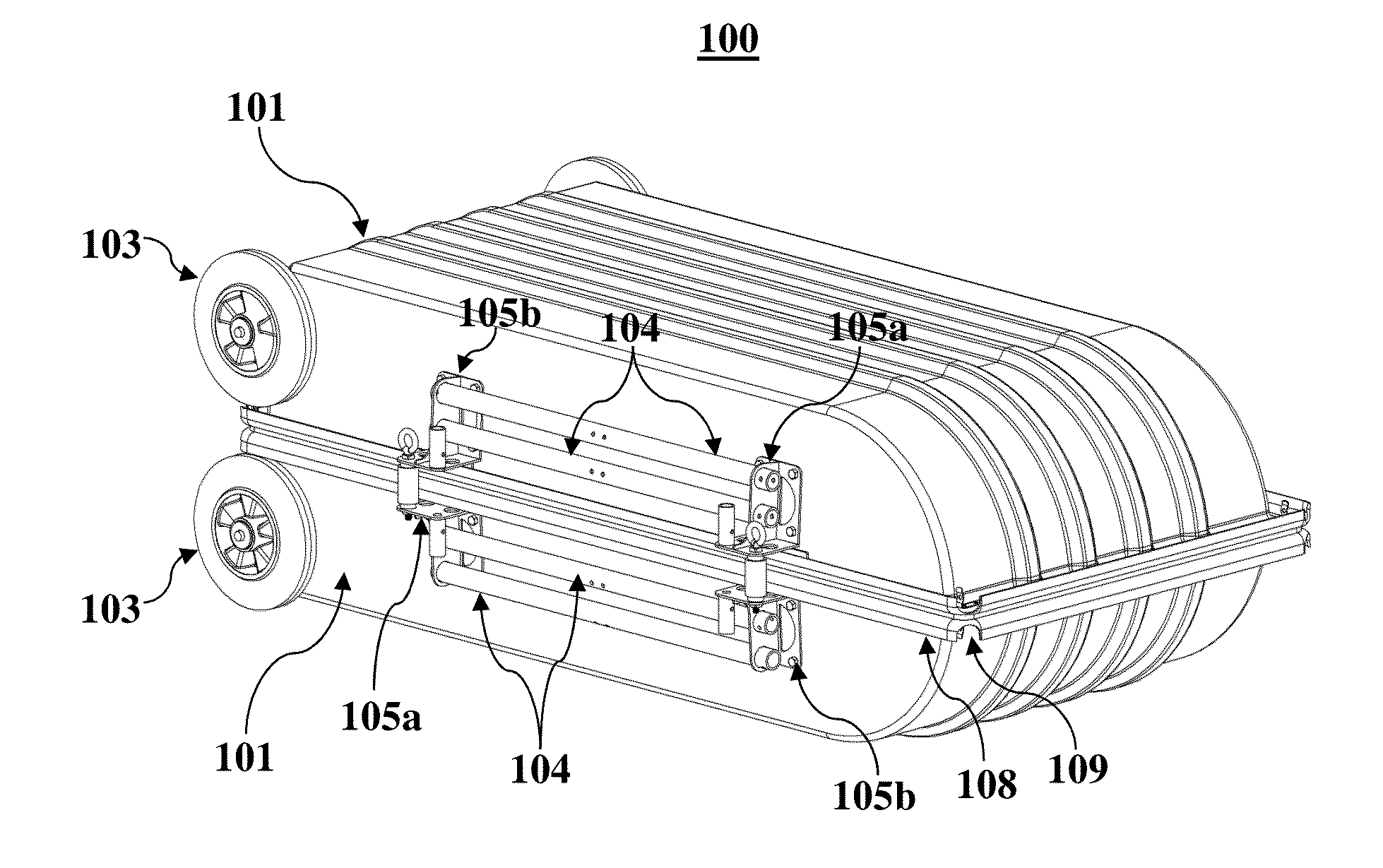
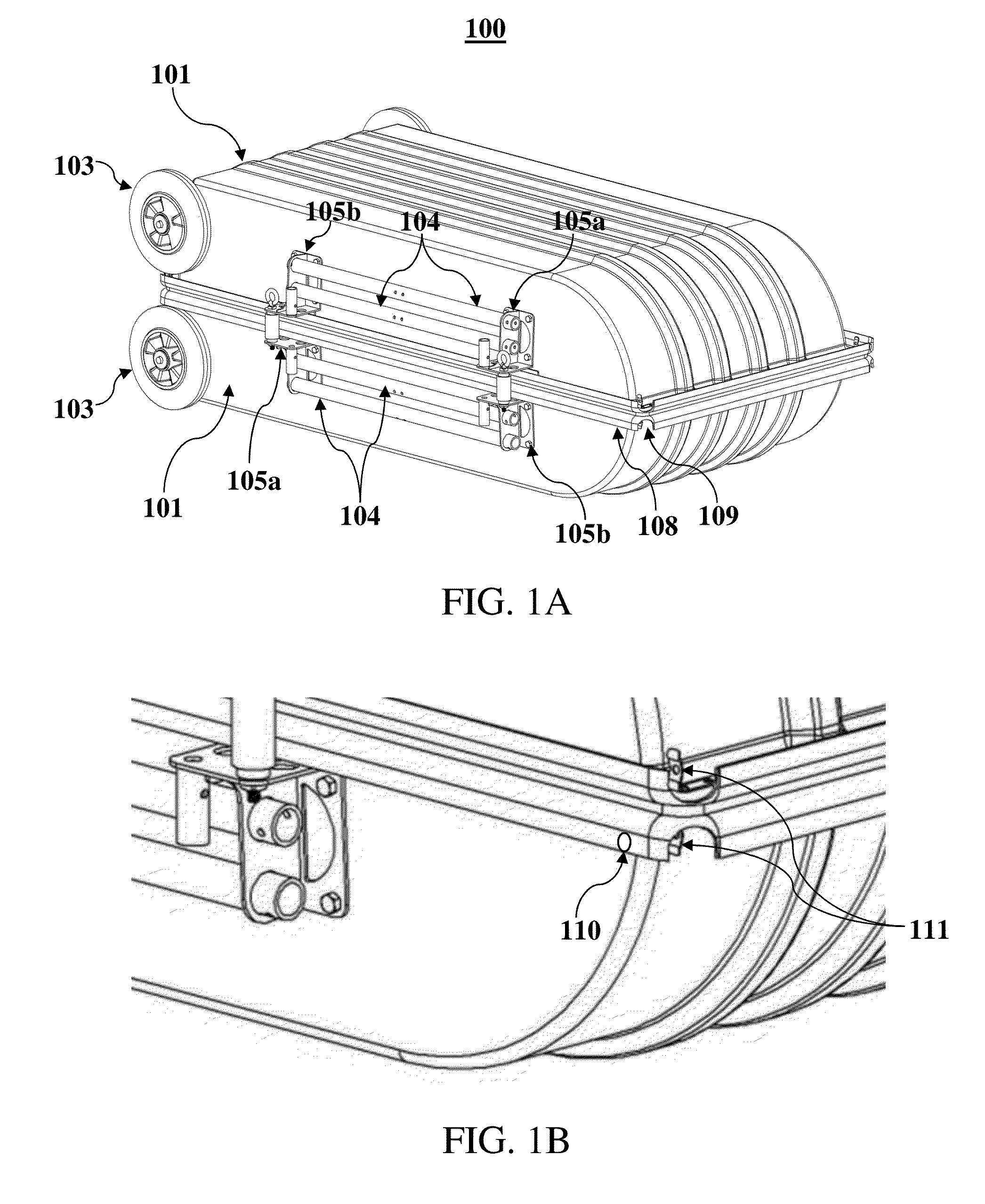
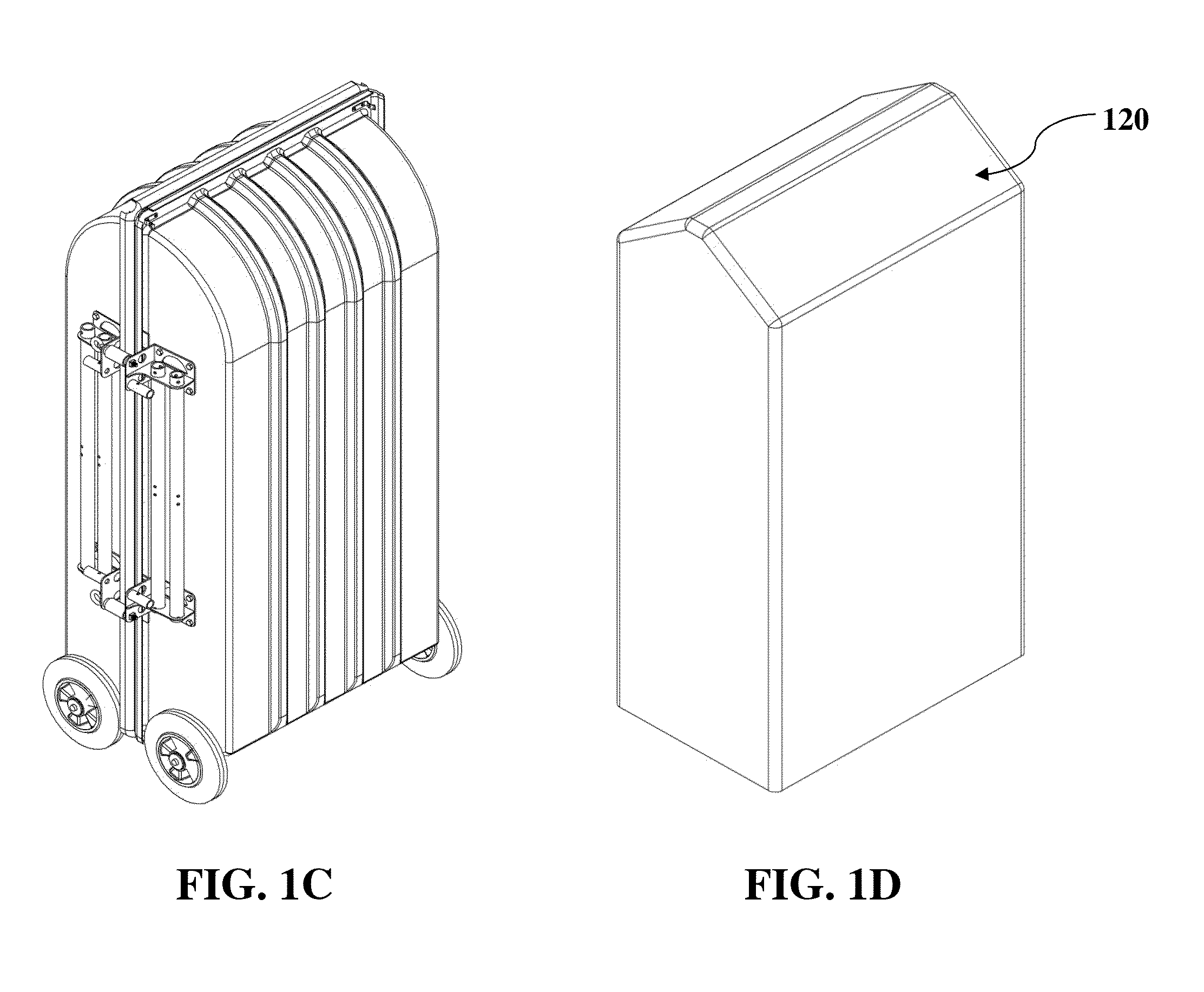
[0032]The present invention is directed to a multi-function cart for storing and transporting emergency, camping, recreational, or other supplies. The multi-function cart serves initially as a mobile storage container having a compact design that allows the storage container to be stored in many different locations including inside or outside the home, business, institution, church, or other buildings, and above or below ground such as on a deck or patio, in a shed, garage, or basement, etc. where it can be quickly accessed in case of an emergency or simply for convenience sake. The convenience and cleanliness provided by this product is a key benefit of this device.

[0033]The multi-function cart is convertible from the mobile storage container into various devices that provide functionality to sustain life during or after a disaster, and to clean-up and rebuild after a disaster has occurred. In this manner, the multi-function cart enables victims to maintain a semblance of normalcy ...


PUM


Abstract

A multi-function cart for storing and transporting emergency or other supplies. The multi-function cart comprises a shell and lid or two shells that can be secured together to form a transportable storage container. When separated, each shell is convertible into various configurations that can be used to sustain life during and after a disaster as well as to clean up and rebuild after a disaster has occurred. In this manner, the multi-function cart enables victims to quickly care for themselves, and encourages victims to immediately begin the clean-up and rebuilding process. The multi-function cart can also be used recreationally. Each shell is convertible into different configurations using various tubes. Hub brackets on opposing sides of the shell include adapters to which any of the tubes can be connected. The tubes can be connected to the adapters in an upward or a downward orientation to form different configurations.

Description

CROSS-REFERENCE TO RELATED APPLICATIONS[0001]This application is a continuation-in-part of U.S. patent application Ser. No. 13 / 545,903, titled Multi-Function Cart and filed Jul. 10, 2012, and of U.S. patent application Ser. No. 13 / 545,893, titled Convertible Aid Cart and filed Jul. 10, 2012, both of which claim priority to U.S. Provisional Patent Application No. 61 / 507,978, titled Mobile Adaptable Survival Container, which was filed on Jul. 14, 2011.BACKGROUND[0002]When a disaster occurs, whether natural or man-made, the injury and death toll often depends on how quickly emergency supplies can be delivered to the victims of the disaster. Oftentimes, victims rely on emergency responders outside the disaster zone to supply the necessary supplies. These emergency responders, in some cases, may not be able to reach many victims in a timely fashion such as when the disaster is of great magnitude or widely spread.[0003]For example, if a large number of people are in need of emergency supp...

Claims


Application Information

Patent Timeline
Patent Type & Authority Patents(United States)
IPC IPC(8): B65D21/02B62B1/00A45C9/00B62B5/00B62B5/06B62B1/04A45C5/14B62B15/00B62B1/20B62K27/00B62B3/02A45C5/03B62B1/18B62B1/12
CPCA45C2009/005B62B5/0013B62B5/0079B65D21/0234B62B2206/006B62B5/067B62B1/20B62B15/007A45C2009/007B62K27/003B62K2710/12A45C5/14B62B1/12A45C5/03B62B3/02B62B1/002B62B2205/104B62B1/186A45C9/00B62B15/004B62B13/16B62B13/18
Inventor BENGTZEN, TROY
Owner BENGTZEN TROY
Why Eureka
Try Eureka