Interlocking bone plate system

a bone plate and interlocking technology, applied in the field of orthopedic instruments, can solve the problems of bone plate deformation, bone plate may be forced to display, bone repositioning after surgery may be destructed, etc., and achieve the effect of high stability in the fixation structur

Inactive Publication Date: 2014-12-16
TAICHUNG VETERANS GENERAL HOSPITAL
View PDF11 Cites 54 Cited by
  • Summary
  • Abstract
  • Description
  • Claims
  • Application Information

AI Technical Summary

Benefits of technology

[0007]The present invention has been accomplished under the circumstances in view. It is the main object of the present invention to provide an interlocking bone plate system for healing a broken bone, which provides a highly stable fixation structure.
[0008]To achieve this object of the present invention, an interlocking bone plate system is adapted for fixation of a fracture of a bone comprising a diaphysis, two epiphysises at two distal ends thereof, two metaphysises respectively connected between the diaphysis and the two epiphysises, an outer bone wall and a medullary cavity surrounded by the outer bone wall. The interlocking bone plate system comprises an outer bone plate attached to the bone adjacent to a predetermined area of an outer surface of the bone and comprising at least one first through hole, an inner bone plate set in the medullary cavity of the bone corresponding to the outer bone plate and comprising at least one second through hole corresponding to the at least one first through hole of the outer bone plate, and at least one screw for locking the outer bone plate and the inner bone plate to the bone. Each screw comprises a head for engaging in one the first through hole, and a shank engageable through the outer bone wall of the bone into one the second through hole. Thus, the inner bone plate gives an added support, enhancing the structural strength and lowering the risk of failed surgery.

Problems solved by technology

This fixation method is not stable due to the fact that when the load from the patient during a movement of the patient is greater than the friction force between the bone plate and the surface of the bone, the bone plate may be forced to display, biasing the screws.
Further, if the bone plate is not closely matched in configuration with the bone, or if the screws are fastened excessively tight or the bone bears an excessive load, bone repositioning after surgery may be destructed.
However, the biodynamic effect of the fixation of the aforesaid new locking plate is still obscure.
Further, a locking plate system of this design is quite expensive and requires a specifically designed surgical implement during surgery.
Further, if the bone receives an excessive muscle tension or load after surgery, the fixation cannot sustain inverse deformation of the bone, leading to surgical failure.

Method used


Image

  • Interlocking bone plate system
  • Interlocking bone plate system
  • Interlocking bone plate system

Examples


Embodiment Construction

[0014]By ways of the following examples in conjunction with the annexed drawings, the technical contents and features of the present invention will be fully understood.

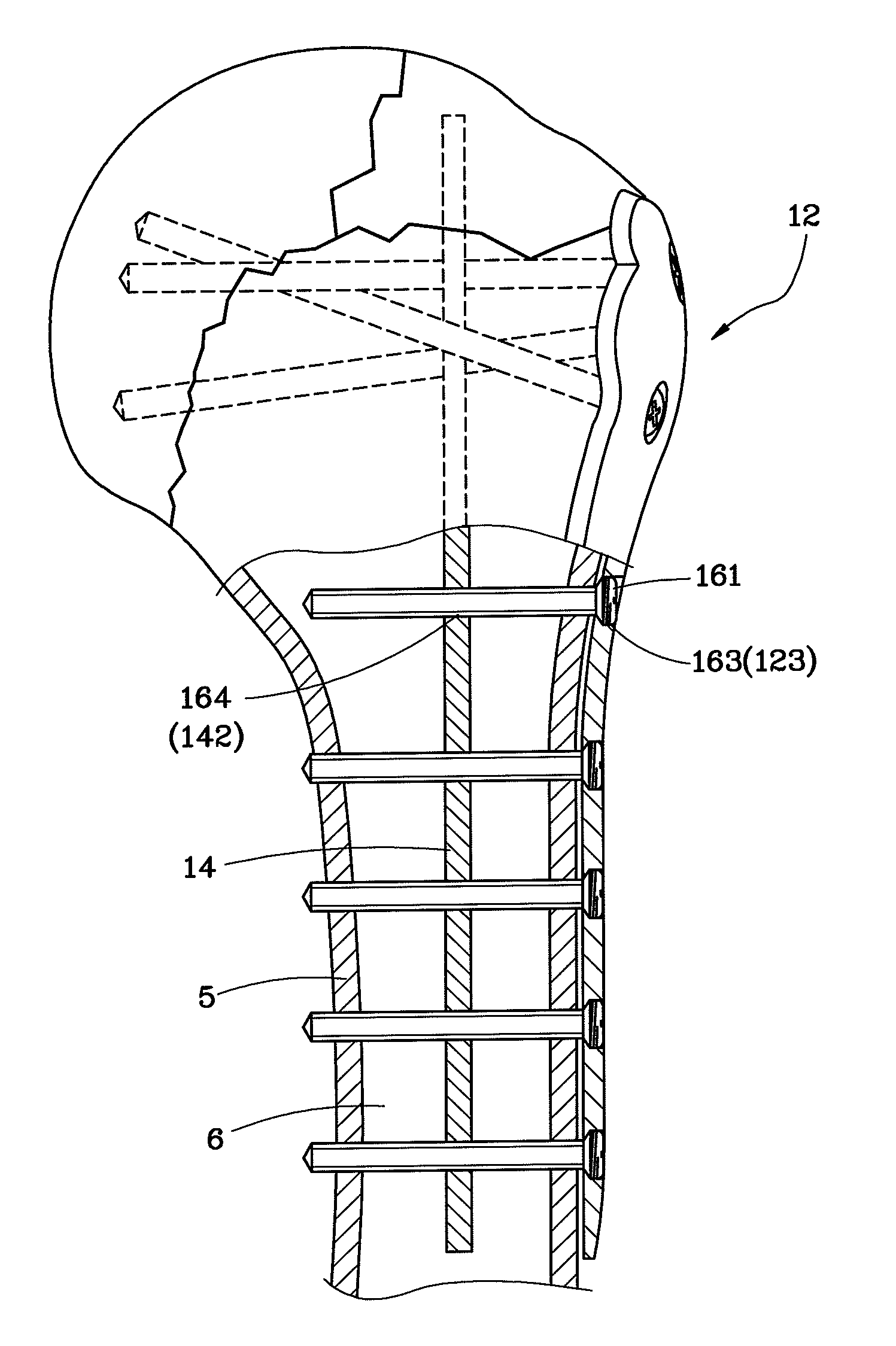
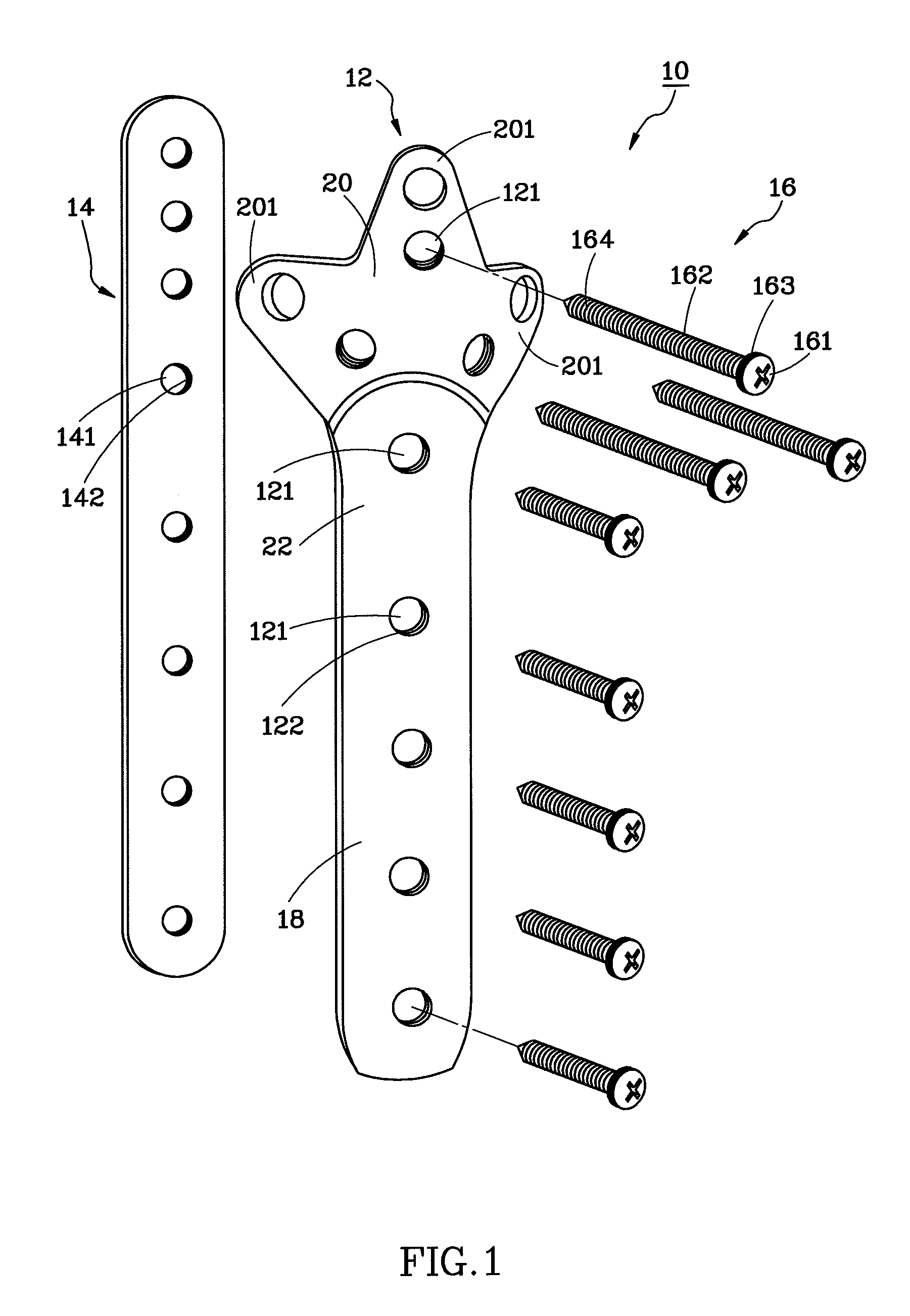
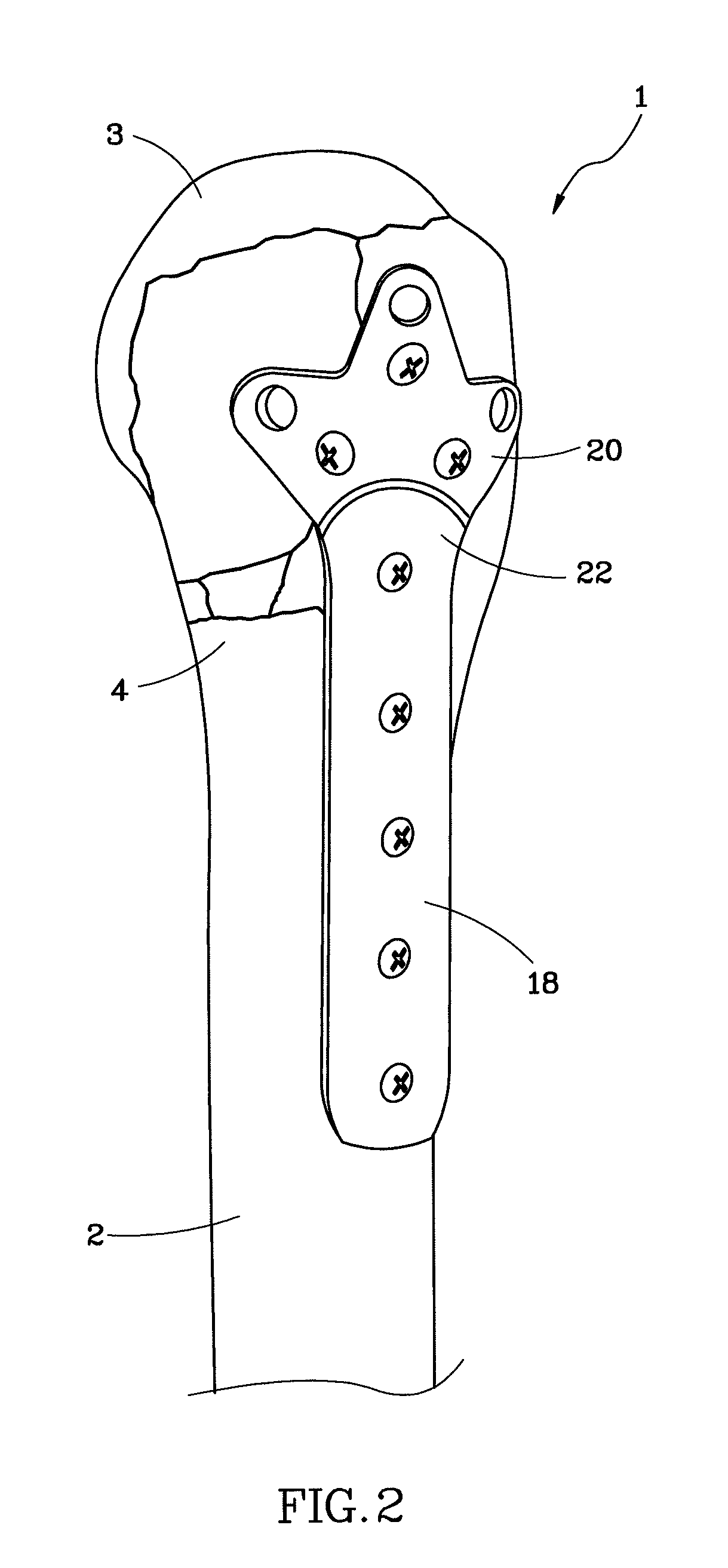
[0015]An interlocking bone plate system 10 is shown for healing a broken bone of a patient, more particularly, for fixation of a comminuted or osteoporotic fracture. As shown in FIG. 2 and FIG. 3, the structure of a bone 1 is symmetric. In the drawings, only one end of the bone 1 is shown for explanation. As illustrated, the bone 1 mainly comprises a diaphysis 2, two epiphysises 3 at the two distal ends thereof, two metaphysises 4 respectively connected between the diaphysis 2 and the two epiphysises 3, a bone wall 5, and a medullary cavity 6 surrounded by the bone wall 5. In this embodiment, the interlocking bone plate system 10 is affixed to one end of the bone 1, comprising an outer bone plate 12, an inner bone plate 14 and a plurality of screws 16.

[0016]As shown in FIGS. 1-3, the outer bone plate 12 is arranged at...


PUM


Abstract

An interlocking bone plate system includes an outer bone plate for being arranged outside a broken bone, an inner bone plate for being installed inside the medullary cavity of the broken bone, and screws for being inserted through and engaged with the outer bone plate and the broken bone and then engaged with the inner bone plate so as to interlock the out and inner bone plates together. The inner bone plate provides an added support in addition to the support provided by the outer bone plate, enhancing the structural strength of the whole bone fixation structure and lowering the risk of failed surgery.

Description

BACKGROUND OF THE INVENTION[0001]1. Field of the Invention[0002]The present invention relates to orthopedic instruments and more particularly, to an interlocking bone plate system for rigidly affixing bone segments.[0003]2. Description of the Related Art[0004]Conventionally, a bone plate and screws are used in surgery for fixation of a comminuted or osteoporotic fracture. By means of the engagement force between the screws and the bone and the friction force between the bone plate and the bone, the bone plate is affixed to the surface of the bone at one side. This fixation method is not stable due to the fact that when the load from the patient during a movement of the patient is greater than the friction force between the bone plate and the surface of the bone, the bone plate may be forced to display, biasing the screws. Further, if the bone plate is not closely matched in configuration with the bone, or if the screws are fastened excessively tight or the bone bears an excessive lo...

Claims


Application Information

Patent Timeline
Patent Type & Authority Patents(United States)
IPC IPC(8): A61B17/72A61B17/58A61B17/80A61B17/86
CPCA61B17/8605A61B17/8061A61B17/8057A61B17/7283A61B17/8625
Inventor LEE, CHENG-HUNGCHANG, CHIH-HANHSIAO, CHIH-KUNHUANG, KUI-CHOUCHEN, CHIH-HUI
Owner TAICHUNG VETERANS GENERAL HOSPITAL
Why Eureka
Try Eureka