Sensor apparatus and electronic apparatus
a technology of electronic equipment and sensor, applied in the direction of instruments, transmission systems, computing, etc., can solve the problems of large number of components, restricted elastic force on the movement amount of the touch surface, and complex structure, and achieve the effect of improving the s/n ratio of the detected signal and large valu
- Summary
- Abstract
- Description
- Claims
- Application Information
AI Technical Summary
Benefits of technology
Problems solved by technology
Method used
Image

Examples
first embodiment
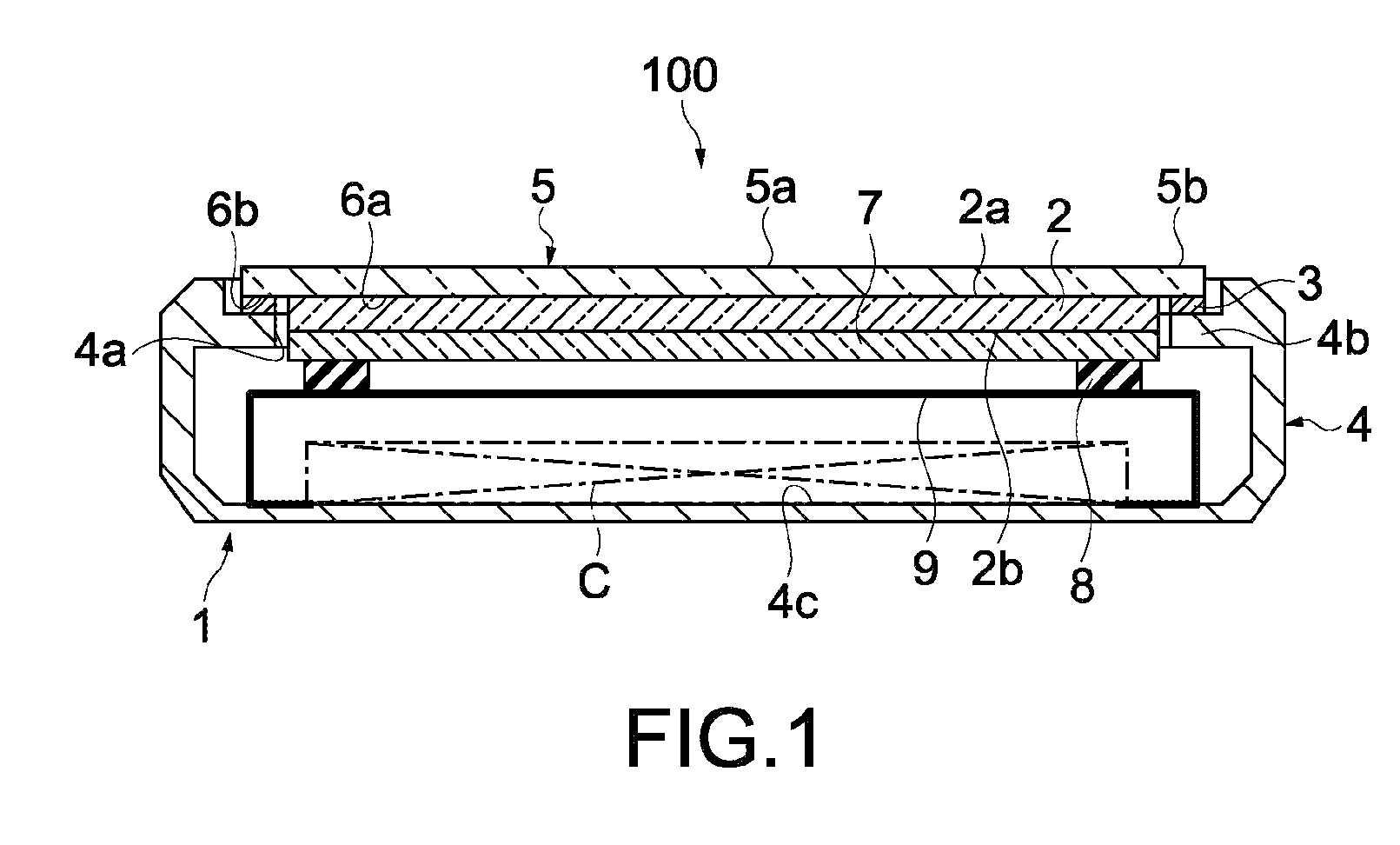
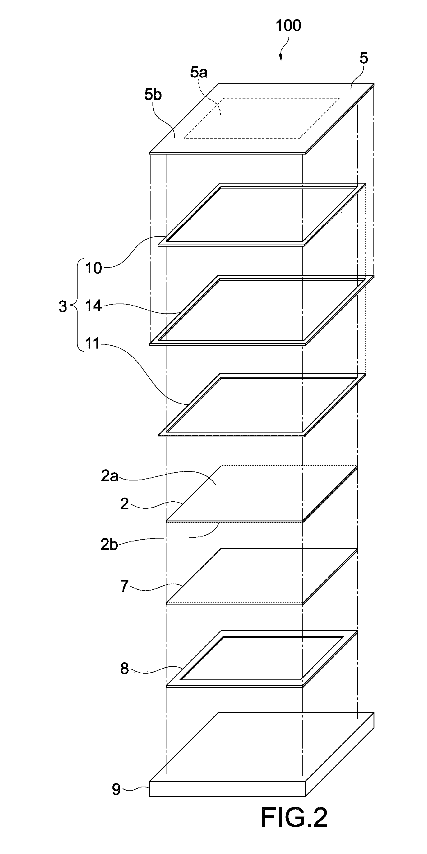
[0086]FIG. 1 is a cross-sectional diagram schematically showing a sensor apparatus according to the present invention. FIG. 2 is an exploded perspective view schematically showing the sensor apparatus shown in FIG. 1. In FIG. 2, an illustration of a frame of the sensor apparatus to be described later is omitted.
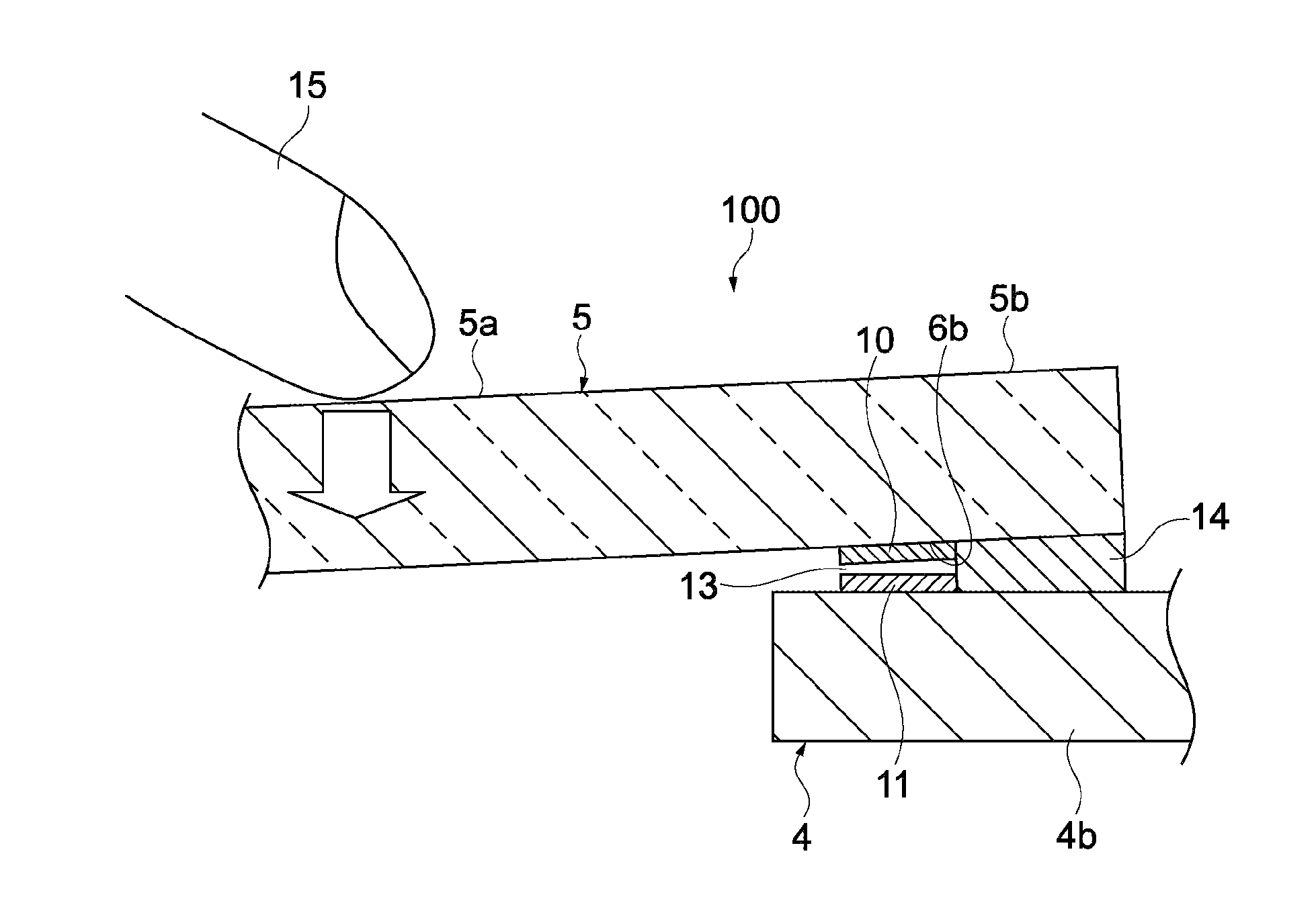
[0087]A sensor apparatus 100 includes a casing 1, a touch panel 2 provided inside the casing 1, and a pressure-sensitive sensor 3. The casing 1 includes a frame 4 on which an opening 4a is formed and a display cover 5 that is fixed to the frame 4 so as to cover the opening 4a. The opening 4a covered by the display cover 5 constitutes a part of an inner space of the casing 1. The touch panel 2 is supported by the display cover 5 so as to be positioned at the opening 4a.
[0088]As shown in FIG. 2, the display cover 5 is rectangular and includes an operation area 5a that is pressed by an operator (not shown) such as a finger and a touch pen and a circumferential area 5b surroundi...
second embodiment
[0120]Next, a sensor apparatus according to the present invention will be described. In the following description, parts having the same structure and operation as those of the sensor apparatus 100 described in the above embodiment will be denoted by the same symbols, and descriptions thereof will be omitted or simplified.
[0121]FIG. 8 is a cross-sectional diagram schematically showing an enlarged pressure-sensitive sensor of the sensor apparatus according to the second embodiment of the present invention. In a sensor apparatus 200 of this embodiment, a structure of the pressure-sensitive sensor is different from that of the sensor apparatus 100 of the first embodiment. Therefore, that point will mainly be described.
[0122]A pressure-sensitive sensor 203 includes the first electrode 10 and the second electrode 11 opposing each other and a differential electrode (third electrode) 216. The differential electrode 216 is provided between the first electrode 10 and the circumferential area...
fourth embodiment
[0142]Next, a sensor apparatus according to the present invention will be described. FIG. 14 is a cross-sectional diagram schematically showing a pressure-sensitive sensor of the sensor apparatus of this embodiment. In a sensor apparatus 400 of this embodiment, the first electrode 10 and the differential electrode 216 are provided while sandwiching the touch panel 2 bonded to the inner surface 6 of the display cover 5.
[0143]As shown in FIG. 14, the differential electrode 216 is provided on the upper surface 2a of the touch panel 2. Therefore, the differential electrode 216 is provided between the upper surface 2a of the touch panel 2 and the inner surface 6b of the circumferential area 5b of the display cover 5. The differential electrode 216 may be bonded to the upper surface 2a of the touch panel 2 and the inner surface 6b of the circumferential area 5b via an adhesive, for example. Alternatively, a metal paste or the like printed on the upper surface 2a of the touch panel 2 or th...
PUM
 Abstract
Description
Claims
Application Information
 - R&D
- Intellectual Property
- Life Sciences
- Materials
- Tech Scout
- Unparalleled Data Quality
- Higher Quality Content
- 60% Fewer Hallucinations
Browse by: Latest US Patents, China's latest patents, Technical Efficacy Thesaurus, Application Domain, Technology Topic, Popular Technical Reports.
© 2025 PatSnap. All rights reserved.Legal|Privacy policy|Modern Slavery Act Transparency Statement|Sitemap|About US| Contact US: help@patsnap.com