
Sliding door stopper system

a technology for sliding doors and stoppers, applied in the direction of hinges, wing accessories, manufacturing tools, etc., can solve the problems of door derailment, door may derail, and eye-pleasant appeal,

Active Publication Date: 2014-12-23
FLEURCO PRODS
View PDF35 Cites 11 Cited by
  • Summary
  • Abstract
  • Description
  • Claims
  • Application Information

AI Technical Summary

Benefits of technology

The patent describes a sliding door stopper assembly that allows the door to be easily removed from its rod, while also preventing the door from moving vertically or horizontally when in use. The assembly includes a stopper member attached to the rod and a bumper attached to the door, which work together to keep the door secure. Additionally, there is a sliding door security system that includes a striker member and a stopper member, which work together to prevent any motion of the door.

Problems solved by technology

The frames are typically bulky and metallic, causing an unpleasant appeal to the eye, as well as providing a surface for soap scum to form.
However, this may also create a risk of the sliding door being derailed as a result of rapid opening and / or hitting the stopper.
There is a risk that upon impact with a stopper, the sliding door may “jump” or move such that the sliding door may derail.
Given that some sliding doors are made of glass, are heavy and fragile, derailment of the sliding door may result in serious injury or risk of injury, as well as damage to the sliding door.

Method used


Image

  • Sliding door stopper system
  • Sliding door stopper system
  • Sliding door stopper system

Examples


Embodiment Construction

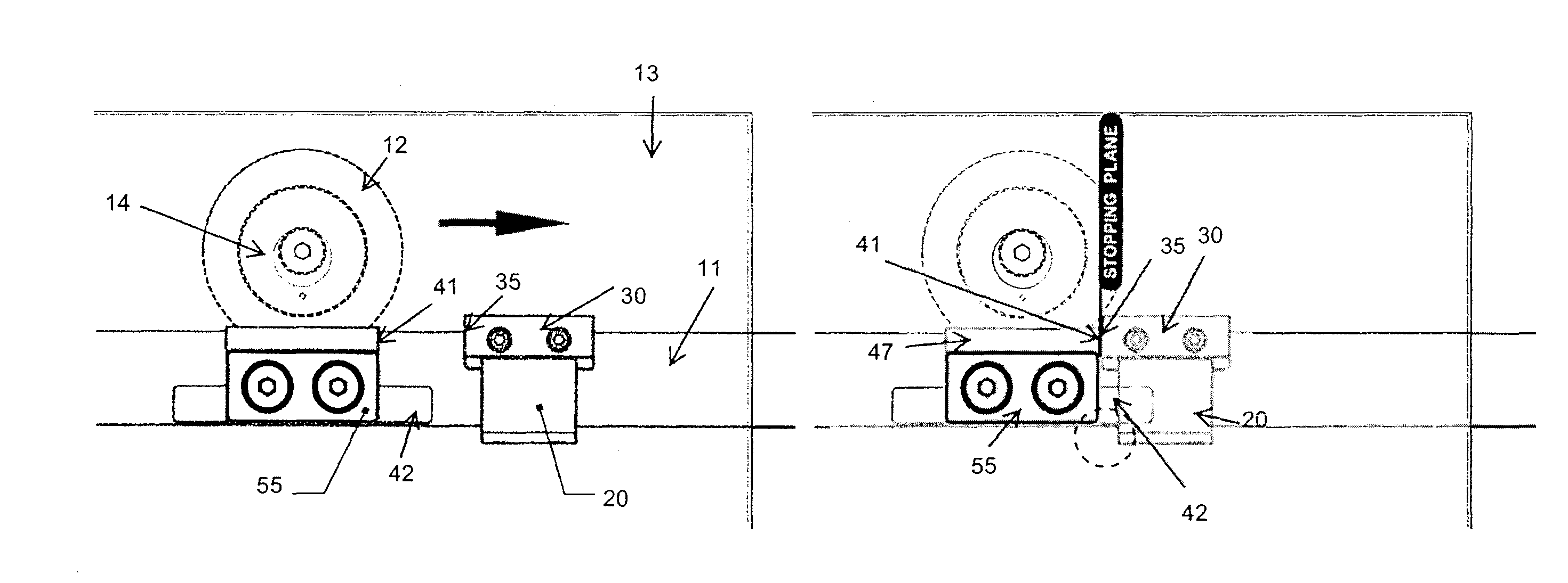
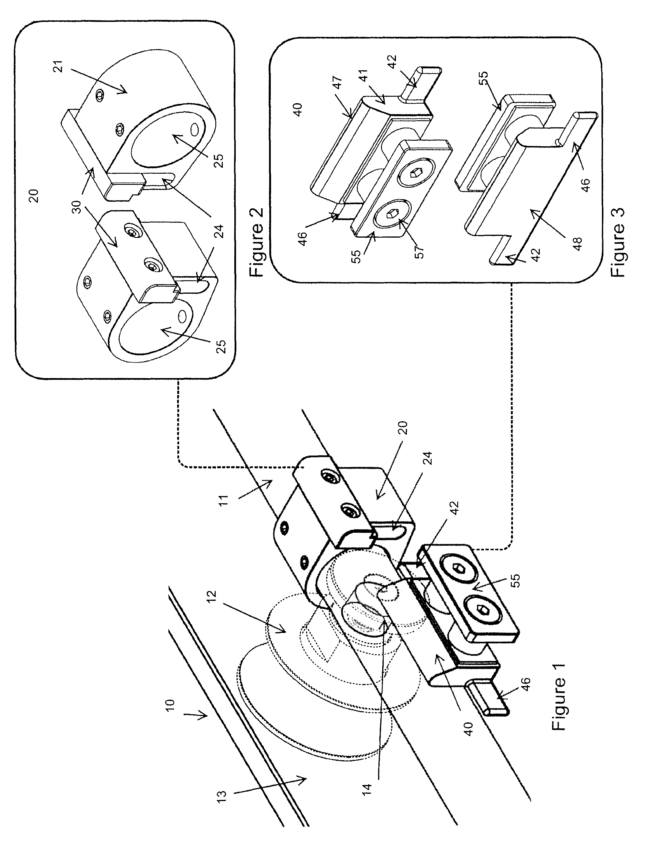
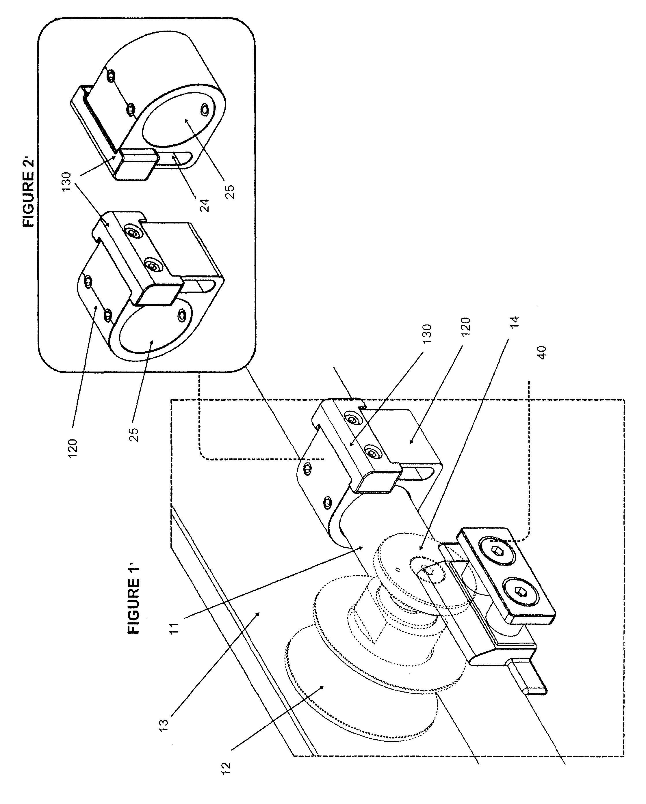
[0056]Referring now to FIG. 1, a sliding door stopper system 10 is shown. Sliding door 13, made of tempered glass, has a wheel or roller 12 allowing it to ride along rod 11. Although sliding door 13 has one roller 12 proximate one end of the sliding door 13, preferably said sliding door 13 will have another roller 12, proximate the other end of the sliding door 13, distant said first roller 12. The number of rollers 12 on said sliding door 13 may depend upon the weight and / or length of the sliding door 13. Roller 12 may be attached to the sliding door 13 by means known in the art. In this instance, the roller 12 is attached to the sliding door 13 by attachment member 14. Rod 11 provides a surface for the sliding door 13 to move along via the roller 12, from an open position to a closed position, and any position between, and supports the sliding door 13. The rod 11 has attached thereto, stopper 20. The stopper 20 prevents the sliding motion of the sliding door 13 beyond a predetermi...


PUM


Abstract

A sliding door assembly for use with a tub or shower enclosure, said assembly comprisinga rod, having a first end and a second end extending along said enclosure; at least one door, having a top, bottom, first end, second end, first surface and second surface;at least one roller attached to said door at a predetermined position and slidably engaging said rod; a stopper attached to said rod, at a predetermined position; a striker attached to said door, at a predetermined position; said striker further comprising at least one striking member; said stopper further comprising at least one striking member receiver;wherein when said door is in a first position, said at least one striking member and said at least one striking member receiver are not engaged and when said door is in a second position, said at least one striking member and said at least one striking member receiver are engaged, preventing said at least one door from substantial horizontal and vertical movement along said rod.

Description

FIELD OF THE INVENTION[0001]The present invention relates generally to a stopper system for sliding door panels used in enclosures, in particular shower and tub enclosures. More specifically it relates to a stopper system for sliding door panels that are suspended from an overhead track wherein said stopper system comprises an anti-derailing component.BACKGROUND[0002]Sliding doors are commonly used for shower and tub enclosures, closets, room dividers, etc. A sliding door system may include one sliding door, one sliding and one stationary door, two sliding doors and any of the combinations of sliding and still doors. A typical sliding door installation is comprised of a frame enclosing two or more sliding doors movable within the frame. Roller assemblies are usually attached to the top edges of the sliding doors which ride along a track forming part of the frame. The frames are typically bulky and metallic, causing an unpleasant appeal to the eye, as well as providing a surface for ...

Claims


Application Information

Patent Timeline
Patent Type & Authority Patents(United States)
IPC IPC(8): E05D13/00E05F5/00
CPCE05Y2800/748E05D2005/0253E05D15/063E05D5/0246E05Y2900/114E05F5/003E05Y2800/16E05Y2800/672E05Y2900/00Y10T16/61Y10T16/628
Inventor SCHACHTER, ROBERTPHAM, CHI HAISCHATZ, KARINALEE, NICHOLAS
Owner FLEURCO PRODS
Learn More