Cutting insert, cutting tool, and method of manufacturing machined product using the same

a technology of cutting tools and cutting inserts, which is applied in the direction of manufacturing tools, shaping cutters, metal working devices, etc., can solve the problems of deterioration of the smoothness of the machined surface (bottom surface) of the workpiece, and achieve the effect of shortening the first inclined cutting edge, high smoothness and large cut depth

Active Publication Date: 2014-12-23
KYOCERA CORP
View PDF22 Cites 12 Cited by
  • Summary
  • Abstract
  • Description
  • Claims
  • Application Information

AI Technical Summary

Benefits of technology

[0004]An object of the present invention is to provide a cutting insert and a cutting tool, which allow the machined surface of the workpiece to be cut with high smoothness, and a method of manufacturing a machined product using the cutting tool.
[0008]In the cutting insert according to the foregoing embodiment, the second flat cutting edge is located from the first intersection region to the second intersection region, and has the lowermost portion in the first intersection region in the side view. Therefore, even when the cutting insert is attached to the holder by setting the axial rake angle of the cutting insert to a negative value, the second flat cutting edge can be positioned substantially parallel to the machined surface of the workpiece over the entire length of the second flat cutting edge, thus allowing the machined surface of the workpiece to be cut with high smoothness. Additionally, not only the cutting edge portion (the first inclined cutting edge) located in the second intersection region, but also the cutting edge portion (the curved cutting edge) located in the first intersection region is usable as a part of the second flat cutting edge. This ensures the desired length of the second flat cutting edge while relatively shortening the first inclined cutting edge. Consequently, the entire length of the second major cutting edge can be further elongated, thus ensuring a large depth of cut.

Problems solved by technology

There is therefore a risk of deterioration of the smoothness of a machined surface (bottom surface) of a workpiece.

Method used


Image

  • Cutting insert, cutting tool, and method of manufacturing machined product using the same
  • Cutting insert, cutting tool, and method of manufacturing machined product using the same
  • Cutting insert, cutting tool, and method of manufacturing machined product using the same

Examples


Embodiment Construction

[0016]

[0017]An embodiment of the cutting insert (hereinafter referred to as an “insert” in some cases) according to the present invention is described in detail below with reference to FIGS. 1 to 3.

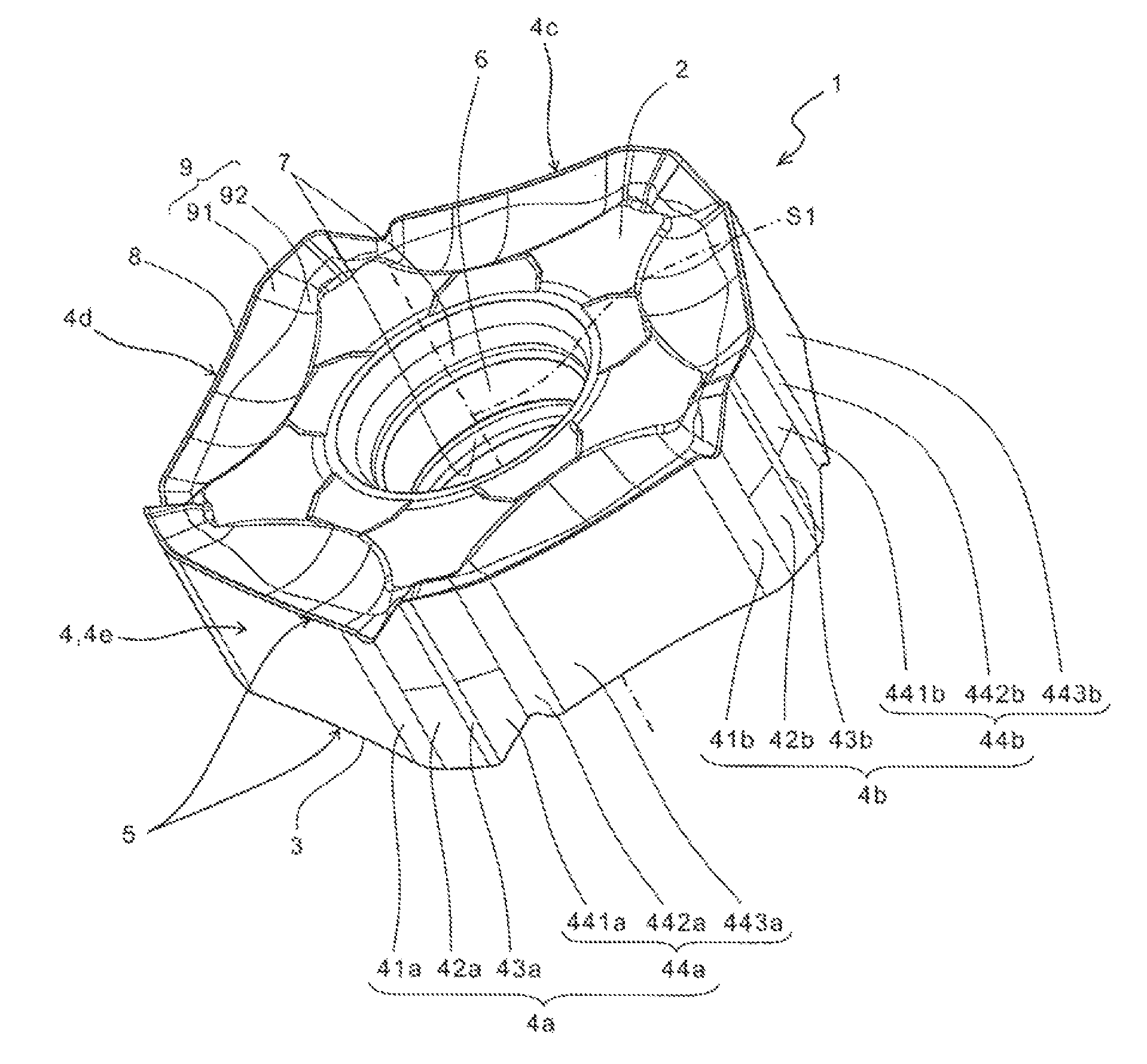
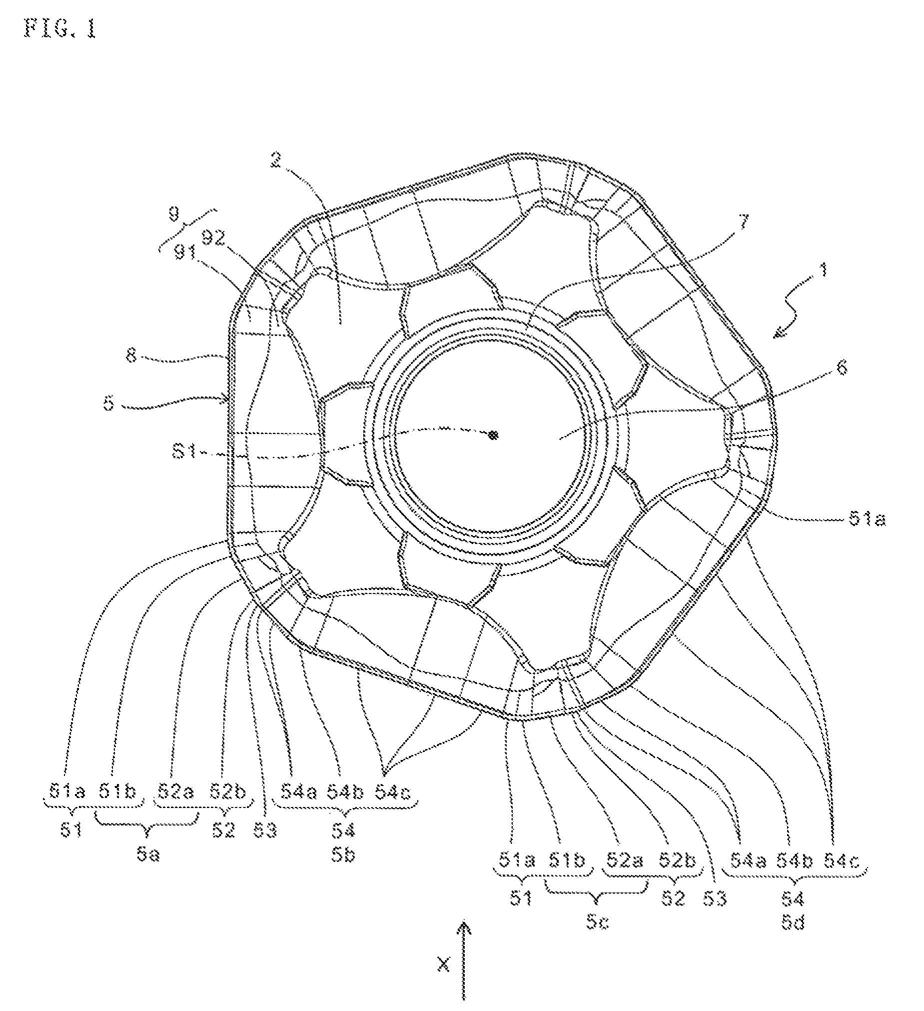
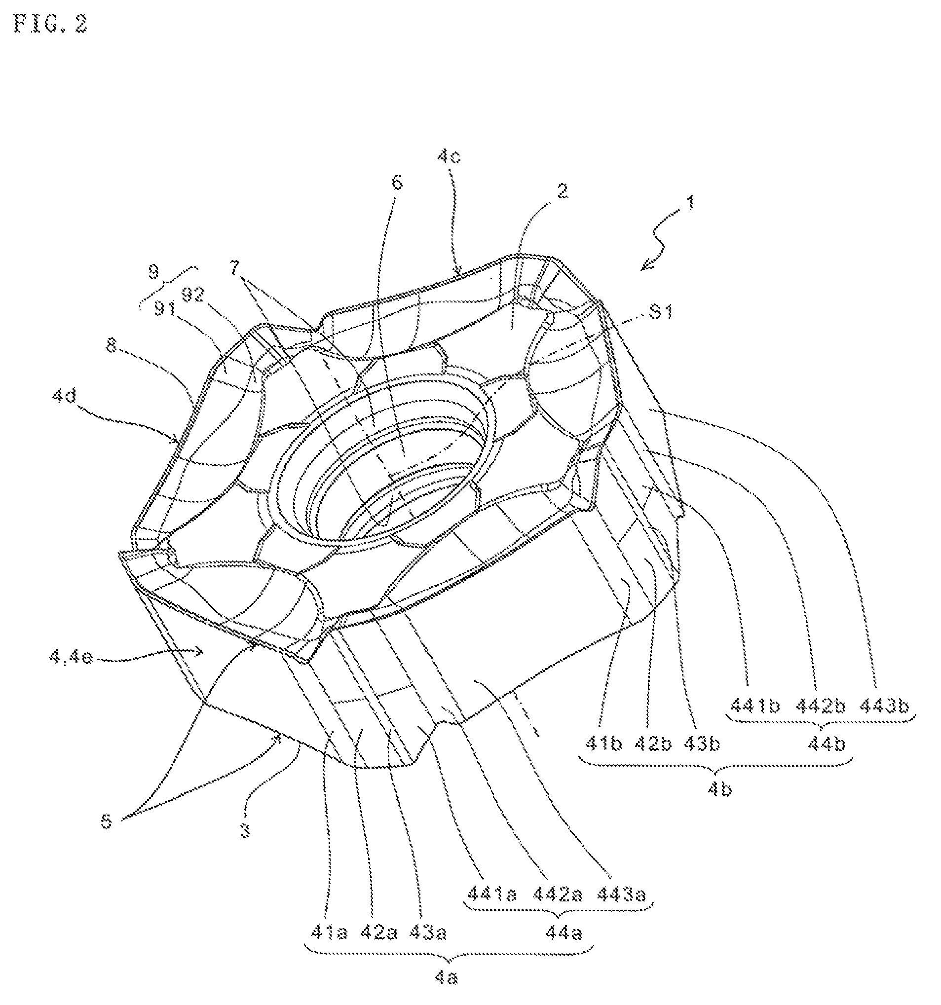
[0018]As shown in FIGS. 1 and 2, the insert 1 of the present embodiment generally includes a top surface 2, a lower surface 3, a side surface 4 connected to the top surface 2 and the lower surface 3, and a cutting edge 5 located in an intersection region of the top surface 2 and the side surface 4. As shown in FIG. 3(b), a second flat cutting edge 5c included in the cutting edge 5 is located from a first intersection region L1 to a second intersection region L2 in the intersection region, and has a lowermost portion V in the first intersection region L1 in a side view.

[0019]The insert 1 has the above configuration. Therefore, even when the insert 1 is attached to a holder 21 shown in FIG. 4 by setting the axial rake angle thereof to a negative value with respect to the holder 21, as shown...


PUM

PropertyMeasurementUnit
cutting edge angleaaaaaaaaaa
angleaaaaaaaaaa

Abstract

A cutting insert with a first flat and major cutting edges in order in an intersection region of a first side surface and an upper surface, and a second flat and major cutting edges in order in an intersection region of a second side surface and upper surface. The first and second side surfaces include respective first and second chamfered side surfaces, respective first and second corner side surfaces, and respective first and second major side surfaces in order. The intersection region of the second side surface and upper surface includes a first intersection region of the second chamfered side surface and upper surface, and a second intersection region of the second corner side surface and upper surface. The second flat cutting edge is located from the first intersection region to the second intersection region, and has a lowermost portion in the first intersection region in a side view.

Description

TECHNICAL FIELD[0001]The present invention relates to a cutting insert, a cutting tool, and a method of manufacturing a machined product using the same.BACKGROUND ART[0002]Japanese Unexamined Patent Publication No. 9-509104 discloses a cutting insert 1b having a secondary sub cutting edge 5b parallel to a support surface 3, between a major cutting edge 4a and a sub cutting edge 5a, as shown in FIG. 14 in the publication.[0003]However, when the cutting insert 1b is attached to a tool 14 with a negative axial rake angle, the secondary sub cutting edge 5b protrudes toward the front end of the tool 14 than the sub cutting edge 5a. There is therefore a risk of deterioration of the smoothness of a machined surface (bottom surface) of a workpiece.SUMMARY OF THE INVENTION[0004]An object of the present invention is to provide a cutting insert and a cutting tool, which allow the machined surface of the workpiece to be cut with high smoothness, and a method of manufacturing a machined product ...

Claims


Application Information

Patent Timeline
Patent Type & Authority Patents(United States)
IPC IPC(8): B23C5/06B23C5/20B23C5/22
CPCB23C2200/0444B23C2200/164B23C2200/208B23C5/06B23C5/202Y10T407/1906Y10T407/1924Y10T407/22Y10T407/23Y10T409/303808
Inventor ISHI, HIROHISA
Owner KYOCERA CORP
Why Eureka
Try Eureka