Shutter mode for color display devices

a color display device and color display technology, applied in the field of color display devices, can solve the problems of difficult to clear the particles gathered on the driving electrode, and achieve the effect of improving the driving efficiency

Active Publication Date: 2014-12-23
E INK CORPORATION
View PDF126 Cites 81 Cited by
  • Summary
  • Abstract
  • Description
  • Claims
  • Application Information

AI Technical Summary

Benefits of technology

[0006]The present inventors now have found that by increasing the space between two neighboring driving electrodes and adjusting the width of the driving electrodes based on particle loading, particles can be driven horizontally in a more efficient manner. The electrode design of the present invention improves the driving efficiency.

Problems solved by technology

However, in practice, it is difficult to clear the particles gathered on a driving electrode.

Method used


Image

  • Shutter mode for color display devices
  • Shutter mode for color display devices
  • Shutter mode for color display devices

Examples


Embodiment Construction

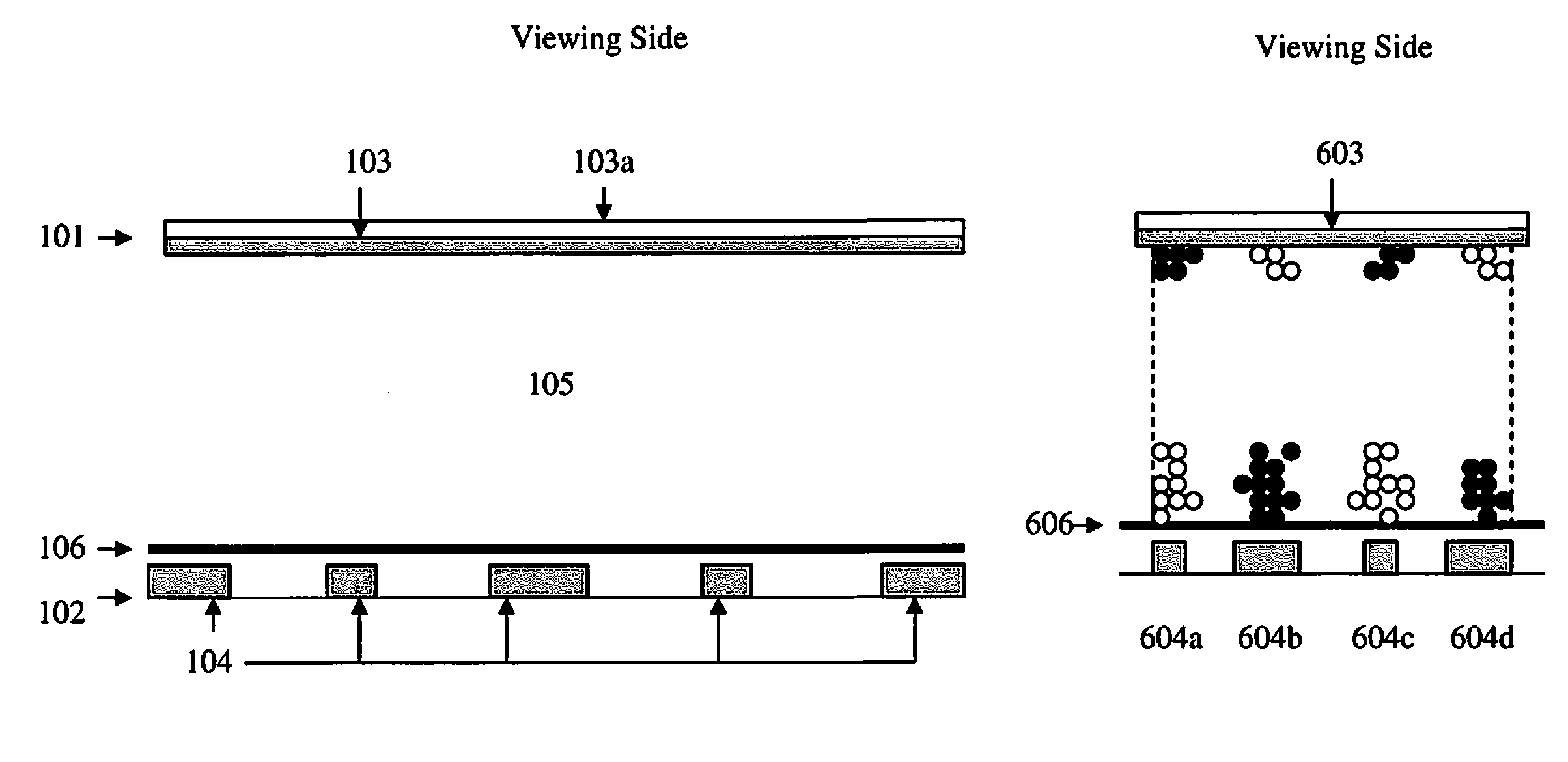
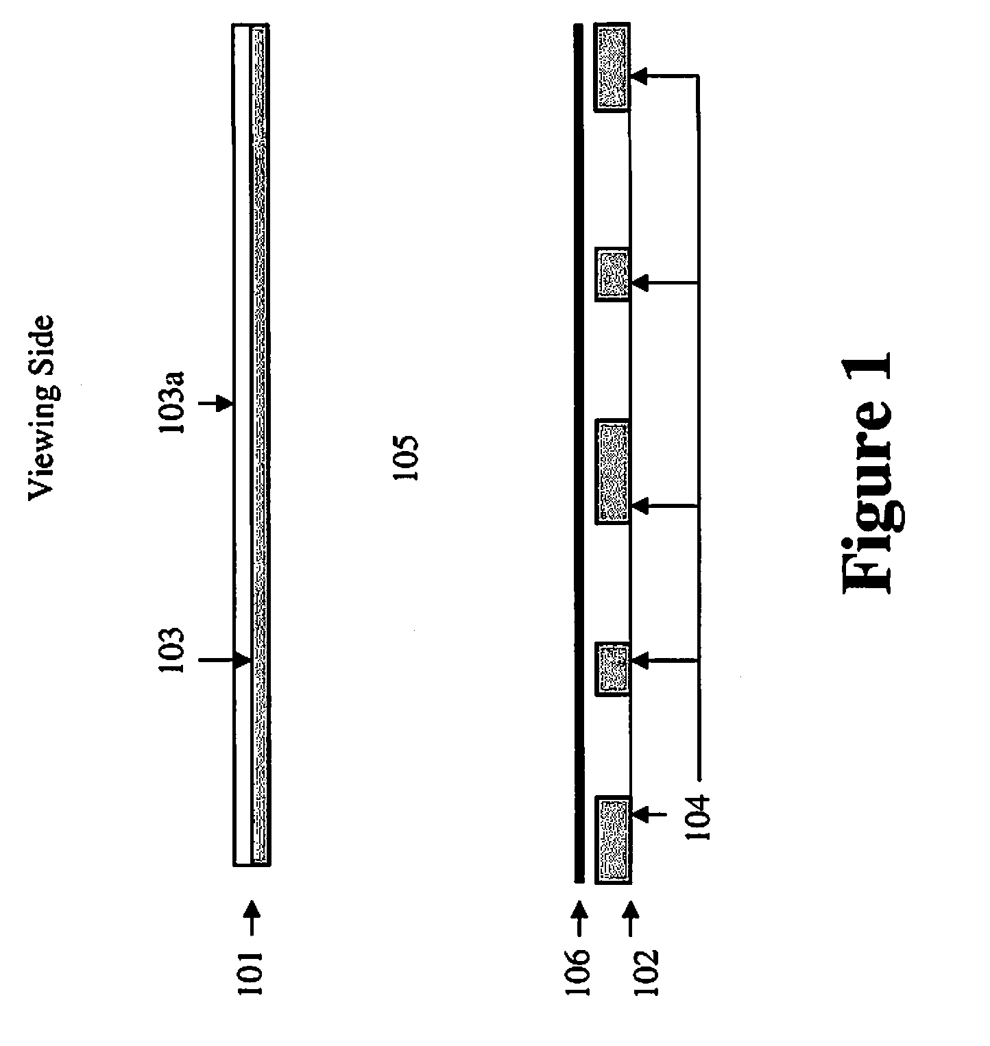
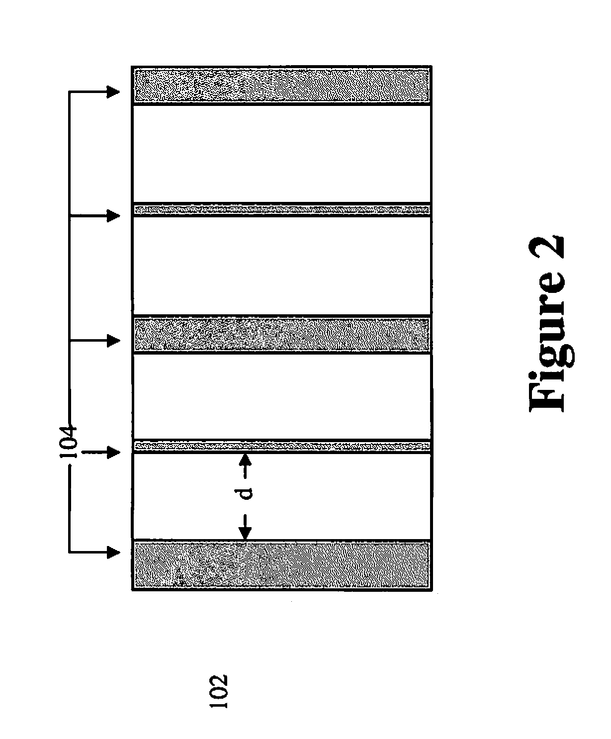
[0034]FIG. 1 depicts a cross-section view of a display device of the present invention. In this design, a display fluid (105) is sandwiched between a first layer (101) and a second layer (102). The first layer comprises a common electrode (103) and the second layer comprises a plurality of driving electrodes (104). The common electrode is usually on a plastic substrate or a piece of glass (103a).

[0035]The display device further comprises a background layer (106) which may be above the second layer (as shown), or underneath the second layer or the second layer may act as the background layer. The formation of the colored background layers is discussed in a section below.

[0036]The display fluid (105) may be an electrophoretic fluid comprising one, two or multiple types of particles. The solvent in the display fluid may be clear and colorless or clear and colored.

[0037]The common electrode (103) in FIG. 1 is usually a transparent electrode layer (e.g., ITO), spreading over the entire t...


PUM

PropertyMeasurementUnit
dielectric constantaaaaaaaaaa
transparentaaaaaaaaaa

Abstract

The present invention is directed to a color display comprising an electrophoretic fluid which comprises one or two types of pigment particles dispersed in a clear and colorless or clear and colored solvent, wherein said electrophoretic fluid is sandwiched between a common electrode and a plurality of driving electrodes. The driving electrodes are kept at a certain distance in order to expose a background layer.

Description

[0001]The present invention is directed to display devices which are capable of displaying multiple color states.BACKGROUND OF THE INVENTION[0002]An electrophoretic display is a device based on the electrophoresis phenomenon of charged pigment particles dispersed in a solvent. The display usually comprises two electrode plates placed opposite of each other and a display fluid comprising charged pigment particles dispersed in a solvent is sandwiched between the two electrode plates. When a voltage difference is imposed between the two electrode plates, the charged pigment particles may migrate to one side or the other, depending on the polarity of the voltage difference, to cause either the color of the pigment particles or the color of the solvent to be seen from the viewing side of the display.[0003]Alternatively, an electrophoretic dispersion may have two types of pigment particles of contrasting colors and carrying opposite charges, and the two types of pigment particles are disp...

Claims


Application Information

Patent Timeline
Patent Type & Authority Patents(United States)
IPC IPC(8): G02B26/00G02F1/167G02F1/16762
CPCG02F2001/1676G02F1/167G02F2001/1678G02F1/16762
Inventor WANG, MINGLIN, CRAIGIVANOV, ROMANZHANG, XIAOJIASPRAGUE, ROBERT A.
Owner E INK CORPORATION
Why Eureka
Try Eureka