Screening for classifying a material

a technology for classifying materials and screening, applied in screening, solid separation, chemistry apparatus and processes, etc., can solve the problems of not being able to meet commercial demands, affecting the performance and longevity of screening, and not being able to efficiently sizing or grading materials, etc., to avoid blinding of screening, enhance the tumbling of material on the screen, and maximize the effect of through pu

Active Publication Date: 2014-12-30
LUMSDEN CORP
View PDF21 Cites 5 Cited by
  • Summary
  • Abstract
  • Description
  • Claims
  • Application Information

AI Technical Summary

Benefits of technology

[0006]Another object of a preferred embodiment of the present invention is to provide a screen that is designed to be self-cleaning to avoid blinding of the screen.
[0007]A further object of a preferred embodiment of the present invention is to enhance tumbling of material on the screen to maximize through put.
[0008]Yet another object of a preferred embodiment of the present invention is to provide a screening that has warp screening elements that are designed to promote self-cleaning of the screen to avoid blinding of the screen.
[0009]Still another object of a preferred embodiment of the present invention is to provide a screening that has warp screening elements with differing spring rates to promote self-cleaning of the screen and avoid blinding of the screen.
[0011]A further object of a preferred embodiment of the present invention is to provide a screening having a first set of warp screening elements with a hardness different from the hardness of a second set of warp screening elements that fosters self-cleaning even where the size and shape of the first set of warp screening elements is the same as the size and shape of the second set of warp screening elements.
[0017]Still another preferred embodiment of the present invention is directed to a screening for use in classifying material flowing through the screening. The screening includes a plurality of warp screening elements. The plurality of warp screening elements includes a first warp screening element having a plurality of undulations. The plurality of warp screening elements further includes a second warp screening element having a plurality of undulations. At least one of the first warp screening element and the second warp screening element has two substantially flat sidewall portions. At least one retaining member is operably associated with the plurality of warp screening elements to form an integral screen segment having a plurality of openings for permitting material to be classified to pass through the openings. The first warp screening element has at least one characteristic different from the second warp screening element to prevent blinding of the integral screen segment. The at least one characteristic affecting movement of the first warp screening element and the second warp screening element when the integral screen segment is used to classify material such that at least one of amplitude and frequency of movement of the first warp screening element is different from at least one of amplitude and frequency of movement of the second warp screening element when the first warp screening element and the second warp screening element are subject to the same operating condition.

Problems solved by technology

Screen design is problematic as numerous factors can adversely impact the performance and longevity of the screen.
For example, the through put of the screen is extremely important as a screen which does not allow for efficient sizing or grading of material will not meet commercial demands although the screen can satisfactorily classify material.
Specifically, where one or more openings in the screen become partially or completely obstructed by material or foreign matter, the performance of the screen greatly deteriorates.
Conventional screens have been unable to address one or more of the aforementioned factors to the detriment of the screen and it commercial success.

Method used


Image

  • Screening for classifying a material
  • Screening for classifying a material
  • Screening for classifying a material

Examples


Embodiment Construction

[0031]The preferred forms of the invention will now be described with reference to FIGS. 1-13. The appended claims are not limited to the preferred forms and no term and / or phrase used herein is to be given a meaning other than its ordinary meaning unless it is expressly stated that the term and / or phrase shall have a special meaning.

FIGS. 1-5

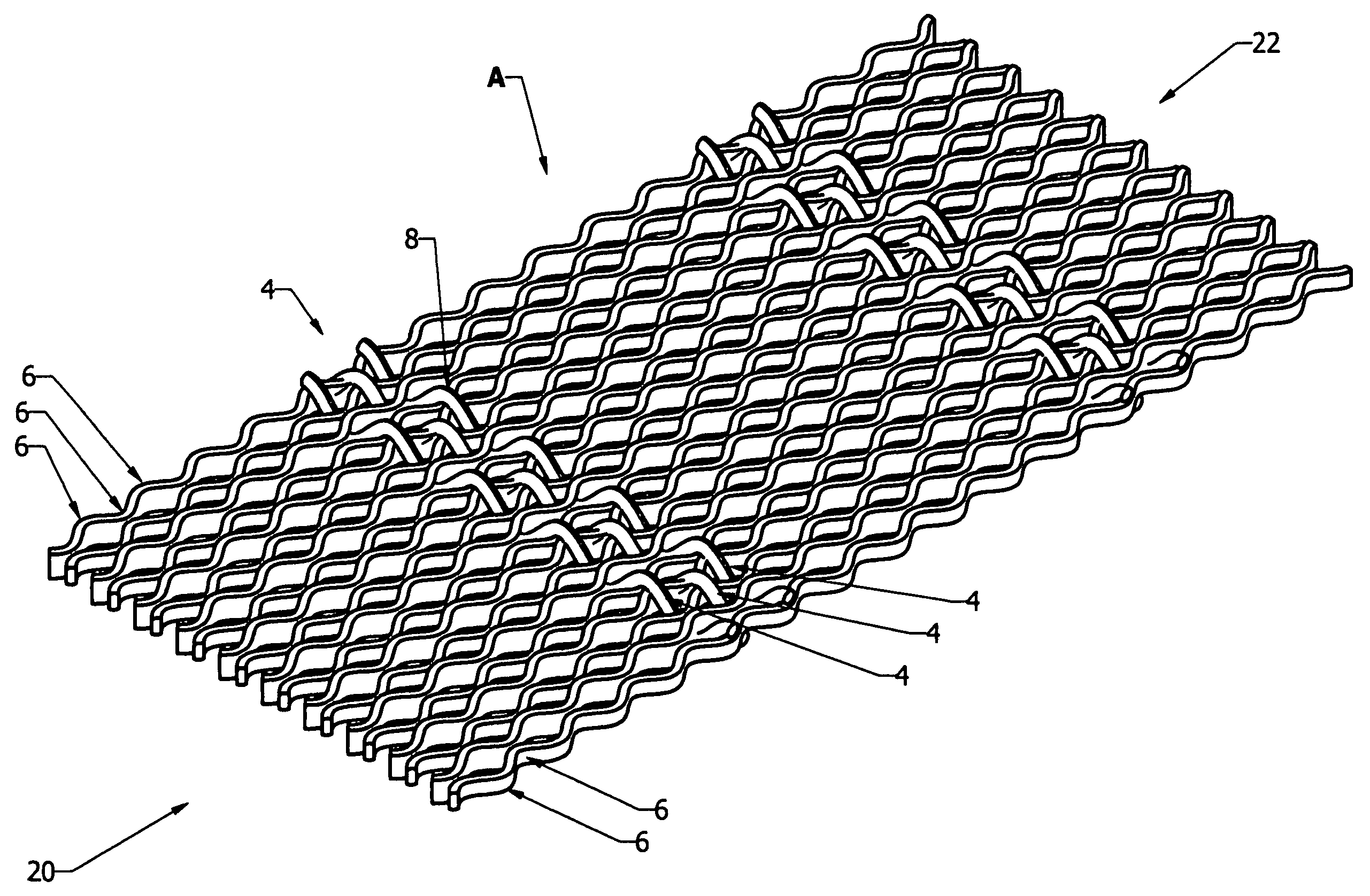
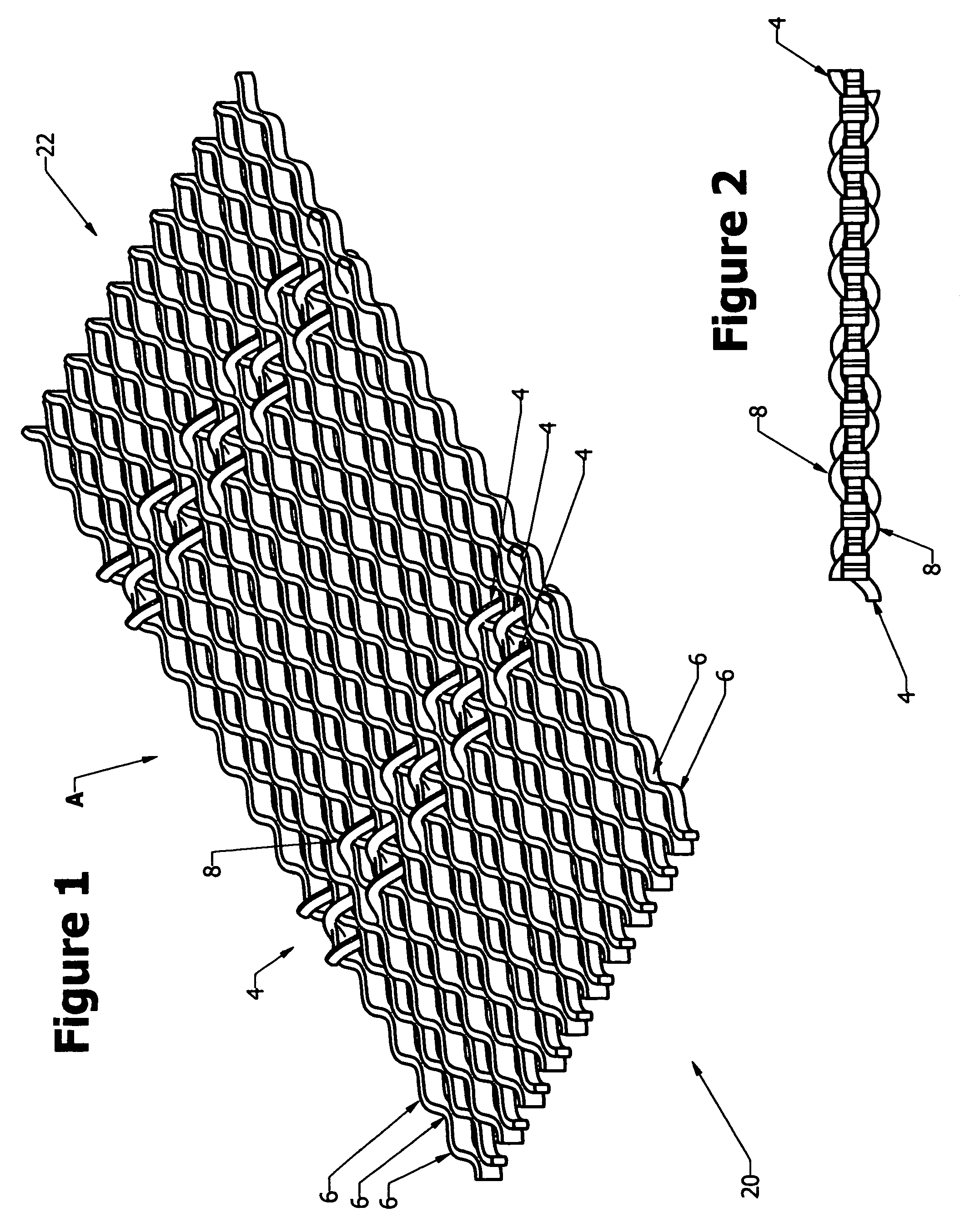
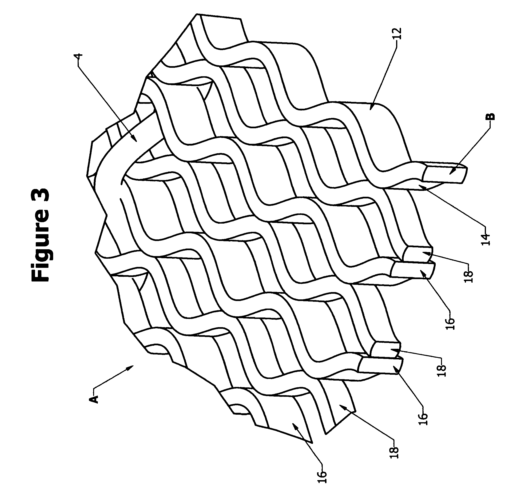
[0032]Referring to FIGS. 1 to 3, a portion of an integral woven wire screening or screen A formed in accordance with a preferred embodiment of the present invention is illustrated in one of many possible configurations. It will be readily appreciated that the size of screen A can be varied as desired. Screen A includes a plurality of interwoven warp screening elements 2 and weft screening elements 4. The warp screening elements 2 are generally oriented perpendicular to the direction of flow of material on the screen surface formed by the uppermost portions of the warp screening elements 2. However, the warp screening elements can be oriented in...


PUM


Abstract

A screening having a plurality of warp elements. The plurality of warp elements includes first and second warp elements each having a plurality of undulations oriented in any desired manner including but not limited to horizontal or vertical. At least one retaining member is operably associated with the plurality of warp elements to form an integral screen segment having a plurality of openings. The first warp element has at least one characteristic different from the second warp element to prevent blinding of the screen segment. The at least one characteristic affecting movement of the first warp element and the second warp element when the screen segment is used to classify material such that at least one of amplitude and frequency of movement of the first warp screening element is different from that of the second warp element when subjected to the same operating condition.

Description

FIELD OF THE INVENTION[0001]The present invention is directed to a screening for classifying a material. More particularly, a preferred embodiment of the present invention is directed to a screening used in a shaker or vibrating screen apparatus that classifies material flowing through one or more screenings. The screening includes a plurality of warp screening elements. Preferably, the plurality of warp screening elements is a plurality of warp wires. The plurality of warp screening elements includes a first warp screening element having a plurality of undulations. The plurality of warp screening elements further includes a second warp screening element having a plurality of undulations. The plurality of undulations of the first and second warp screening elements may be oriented in any desired manner including but not limited to a horizontal orientation and a vertical orientation. At least one retaining member is operably associated with the plurality of warp screening elements to ...

Claims


Application Information

Patent Timeline
Patent Type & Authority Patents(United States)
IPC IPC(8): B07B1/46
CPCB07B1/4681B07B1/4672
Inventor BECK, JEFFREY L.WARDELL, MYRON HENRYKNEPP, BOYD E.
Owner LUMSDEN CORP
Why Eureka
Try Eureka