Noise barrier structure with sound-absorbing and sound-redirecting properties, and high performance sound absorber for use in such structure

a technology of noise barrier and sound absorbing technology, which is applied in the field of noise barriers, can solve the problems of not only porenbeton barriers, but also the inefficiency of acoustic boxes, and achieve the effect of unprecedented effectiveness

Inactive Publication Date: 2015-01-06
URBANTECH
View PDF12 Cites 16 Cited by
  • Summary
  • Abstract
  • Description
  • Claims
  • Application Information

AI Technical Summary

Benefits of technology

[0010]At the same time, and as a consequence thereof, the present invention attains the object of reducing the production, assembly and maintenance costs of the noise structure, also thanks to a particularly simple and practical system for mounting the boxes.
[0013]Advantageously, between two boxes placed and spaced apart one under the other, an Helmholtz resonator effect is also obtained because of the chambers behind the rear walls and the gap between the two boxes, the latter representing the neck of the resonator. This effect in its turn maximizes the effectiveness of the structure.
[0014]In a further advantageous solution, if the boxes are placed in rows, one row above the other, the boxes of a row being staggered with respect to the boxes of an adjacent row, a space is created between two boxes placed in a side-by-side relationship in the same row which, together with the gap formed with a staggered box of an adjacent row, creates a second Helmholtz resonator effect in a direction parallel to the surface of the barrier, the neck of such a second resonator corresponding to the mentioned space between the two boxes placed in a side-by-side relationship.
[0017]If the material has a fibrous structure with unidirectional arrangement of the fibers, for at least some of the mentioned front layers the direction of the fibers can advantageously be set so as to be orthogonal with respect to the rear wall. Preferably, the filling material (for example polyester felt, mineral wool, glass wool) can have—as far as at least some of the front layers are concerned—fibers exposed irregularly on the front ends. Such an internal configuration creates a further effect of acoustic absorption in addition to the normal absorption due to porosity of the filling material and to the traditional cavity resonance inside the box; in fact, the stepped hollow space resulting between the front wall and the front ends of the layers can be compared to a Schroeder diffuser, the effectiveness of which is increased by the fibers exposed on at least some of the layers.
[0018]The combination of the above mentioned sound absorbing effects results in a really unprecedented effectiveness in the field of noise systems for road use, due to the synergic combination of eight effects of acoustic absorption which obviously well surpass the two or three typical effects of traditional systems.

Problems solved by technology

By way of example, noise barriers made of autoclaved aerated concrete (better known with the “porenbeton” trade name), although presenting many technical advantages, generally have quite poor sound absorbing performances.
Such a problem is of course present not only with barriers made of porenbeton, but also with those made of different materials such as, for example, normal concrete.
However, such acoustic boxes are not particularly efficient insomuch as a large number of them needs to be applied to increase the sound absorption properties of the barrier until reaching A4 level, with a consequent increase in costs and difficulties in the production, assembly and maintenance.

Method used


Image

  • Noise barrier structure with sound-absorbing and sound-redirecting properties, and high performance sound absorber for use in such structure
  • Noise barrier structure with sound-absorbing and sound-redirecting properties, and high performance sound absorber for use in such structure
  • Noise barrier structure with sound-absorbing and sound-redirecting properties, and high performance sound absorber for use in such structure

Examples


second embodiment

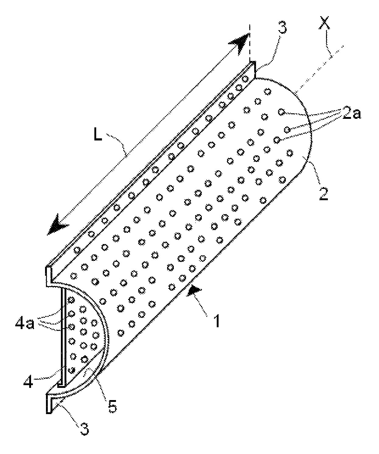
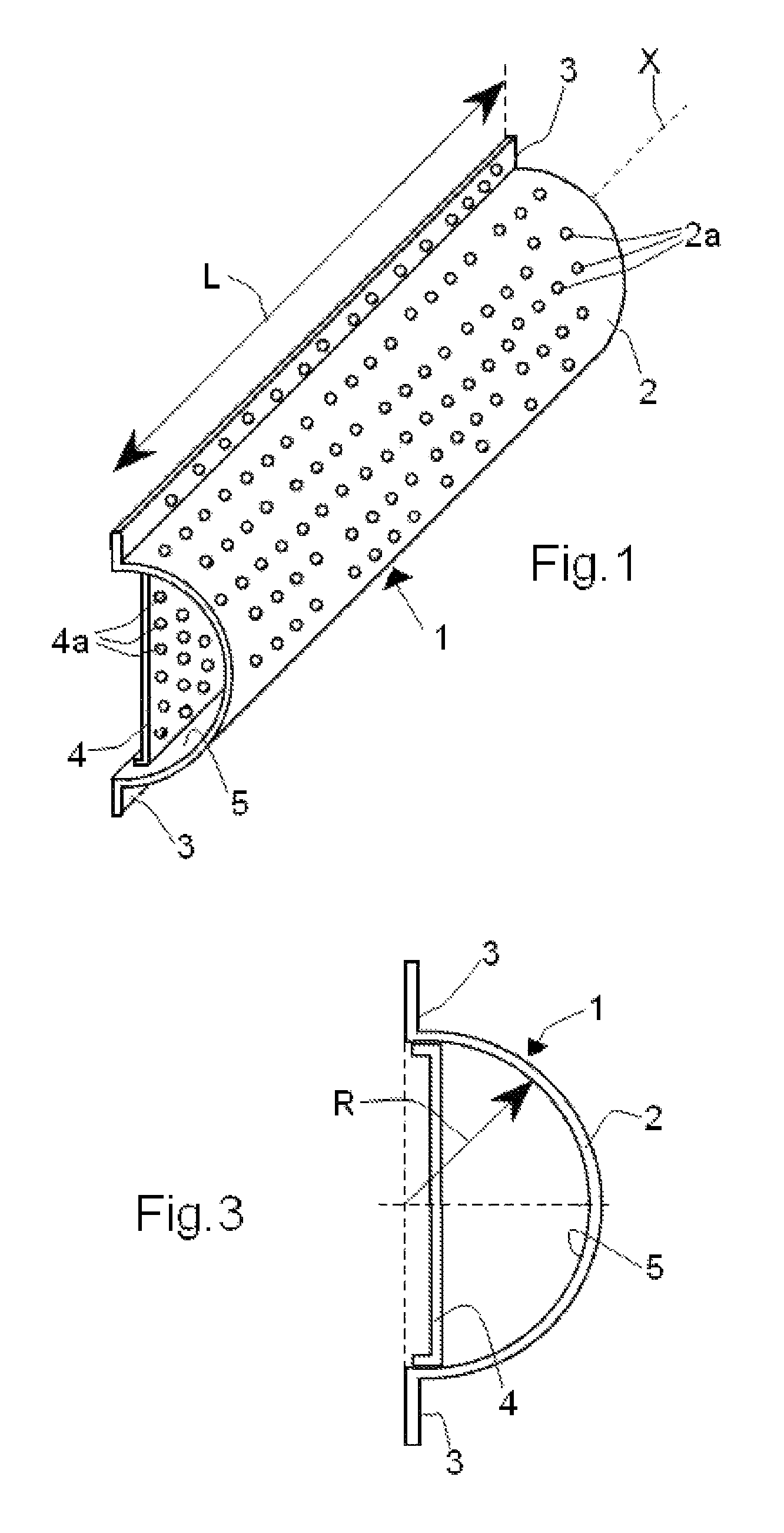
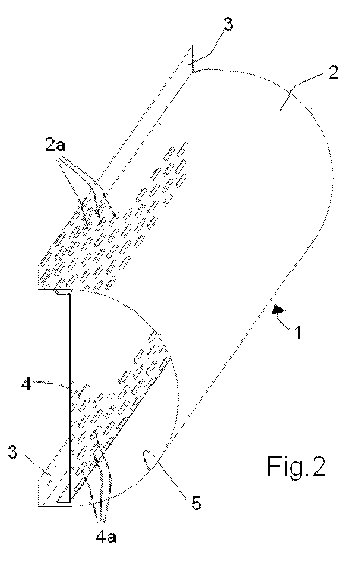
[0037]In the present invention, as schematically shown in FIG. 6, the fastening wings can be omitted and in this case the spaced-apart connection to surface 8a of a barrier 8 (made of a sound redirecting material such as porenbeton or normal concrete) is carried out through studs 9 which project orthogonally from the rear wall 4 and insert by sliding with enlarged heads 9a in tracks 10 (by way of example the so-called Halfen® profiles, which are U-shaped and have inwards folded rims) which are applied directly to barrier 8.

[0038]The sound absorbing box formed by the rear wall 4 and the concave front wall 2 can be made as one or in two separate pieces which are then joined together. It is apparent that any material can be used: aluminum, zinc-plated steel, recycled plastic and so on.

first embodiment

[0039]The distance between the rear wall 4 and the surface 8a of the barrier 8 can be preferably comprised between 2 cm and 9 cm. The technical result of this spacing, which can be obtained, as seen, also with the first embodiment, is to highly increase the sound absorption characteristics because the fraction of sound radiation which is not directly captured by the front wall 2 and is reflected / deviated by the barrier is captured by the rear wall 4 and by the filling 6. Said reflected radiation is represented and indicated at 106 in FIG. 6 and, as can be noted, the peak of the wave 106′ results exactly where the sound absorbing material is placed, thus allowing the box to be particularly effective in the reduction of such a component. Within the above mentioned range, distances between 4 cm and 8 cm, but more specifically and effectively between 3 cm and 4 cm, are particularly indicated for high-frequency noise components (3150-8000 Hz).

[0040]Moreover, the spacing between the rear ...


PUM


Abstract

A noise structure having a barrier made of a generally sound redirecting material defining a surface of the barrier, and a plurality of sound absorbing boxes connected to this surface, each box comprising a rear wall and an extensively perforated front wall, the walls defining a longitudinal channel at least partially occupied by a filling made of a sound absorbing material, in which the rear wall is a substantially flat plane wall assembled parallel to and spaced apart from the surface of the barrier and is in its turn extensively perforated.

Description

CROSS-REFERENCE TO RELATED APPLICATIONS[0001]This application is a 371 of PCT / IB2012 / 05053, filed Feb. 6, 2012, which claims the benefit of Italian Patent Application No. PI2011 A00011, filed Feb. 7, 2011, the contents of each of which are incorporated herein by reference.FIELD OF THE INVENTION[0002]The present invention concerns the technical field of noise barriers.[0003]In particular, this invention relates to a noise structure provided with a special sound absorbing element, or sound absorbing acoustic absorber, which can be applied to selected points of a generally sound redirecting noise barrier.BACKGROUND OF THE INVENTION[0004]Depending on the materials they are made of, noise barriers can have very different sound absorbing or sound redirecting characteristics. By way of example, noise barriers made of autoclaved aerated concrete (better known with the “porenbeton” trade name), although presenting many technical advantages, generally have quite poor sound absorbing performan...

Claims


Application Information

Patent Timeline
Patent Type & Authority Patents(United States)
IPC IPC(8): B64F1/26E01F8/00E04B1/82
CPCE04B1/8209E01F8/0035E01F8/007
Inventor TIZZONI, GIAMPAOLO
Owner URBANTECH
Why Eureka
Try Eureka