
Vehicle restraint system with weighting body

a technology of vehicle restraint and weight, which is applied in the direction of pasturing equipment, applications, and ways, etc., can solve the problems of poor protection characteristics, high dead weight, and high labor intensity, and achieve the effect of improving the deformation characteristics of the base body and the higher restraint level

Active Publication Date: 2015-01-06
BOCHUMER EISENHUTTE HEINTZMANN GMBH & CO BAU UND BET KG
View PDF22 Cites 1 Cited by
  • Summary
  • Abstract
  • Description
  • Claims
  • Application Information

AI Technical Summary

Benefits of technology

The present invention provides a vehicle restraint system that can achieve different levels of restraint through superstructures and different coupling variants, as well as loading or unloading. The system includes a weighting body that can be easily fixed in the base body of the system through fasteners. The advantage of this solution is that the base bodies can be equipped with weighting bodies in a modular fashion, making them easy to store, transport, and install. Depending on the demands on the restraint value of the system, the base bodies can be equipped with single or several weighting bodies.

Problems solved by technology

Protective steel walls that are built according to this design have the disadvantage of possessing a high dead weight.
Several protective steel walls linked end-to-end can have a poor tension strap property in the case of a vehicle impact resulting in a poor protective characteristic.
This system is disadvantageous in that the vehicle restraint system has to be filled with weighting material after being deployed at the desired location.
This filling process is quite elaborate, time-consuming and cost-intensive.
Additionally, the unfavorable weight distribution of the filler inside the container with regard to the vehicle restraint system results in a high center of gravity, depending on the filling degree.

Method used


Image

  • Vehicle restraint system with weighting body
  • Vehicle restraint system with weighting body
  • Vehicle restraint system with weighting body

Examples


Embodiment Construction

[0042]In the Figures, same reference signs are used for same or similar parts, whereby corresponding or comparable advantages are achieved even though, for sake of simplification, a repetitive description is omitted.

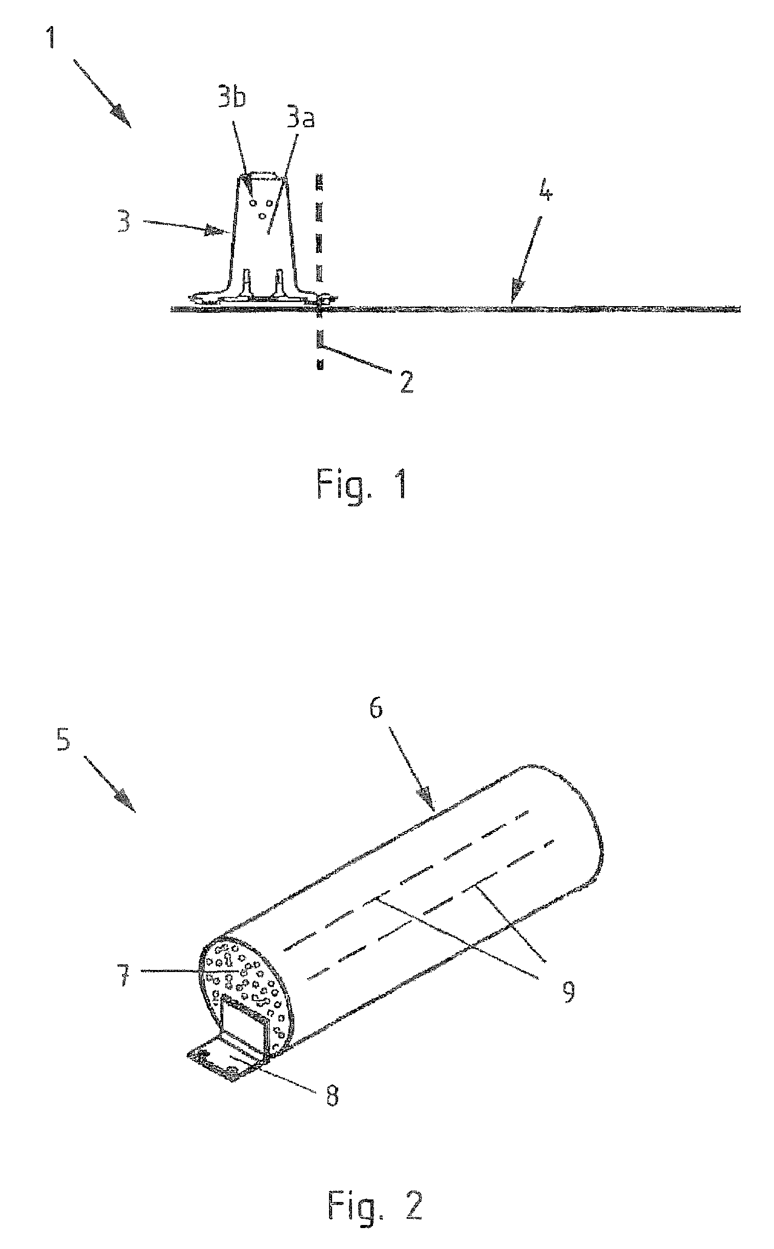
[0043]FIG. 1 shows a vehicle restraint system 1 for roadway delimitation 2 of a road. For this purpose, base bodies 3 are coupled to one another and placed on a road surface 4. A vehicle colliding with the vehicle restraint system 1 is restraint from leaving the road, and driving over the roadway delimitation 2 is prevented reliably. Further, the base body 3 has face plates 3a. The face plates 3a are provided with three holes 3b to connect two base bodies 3 by means of couplers.

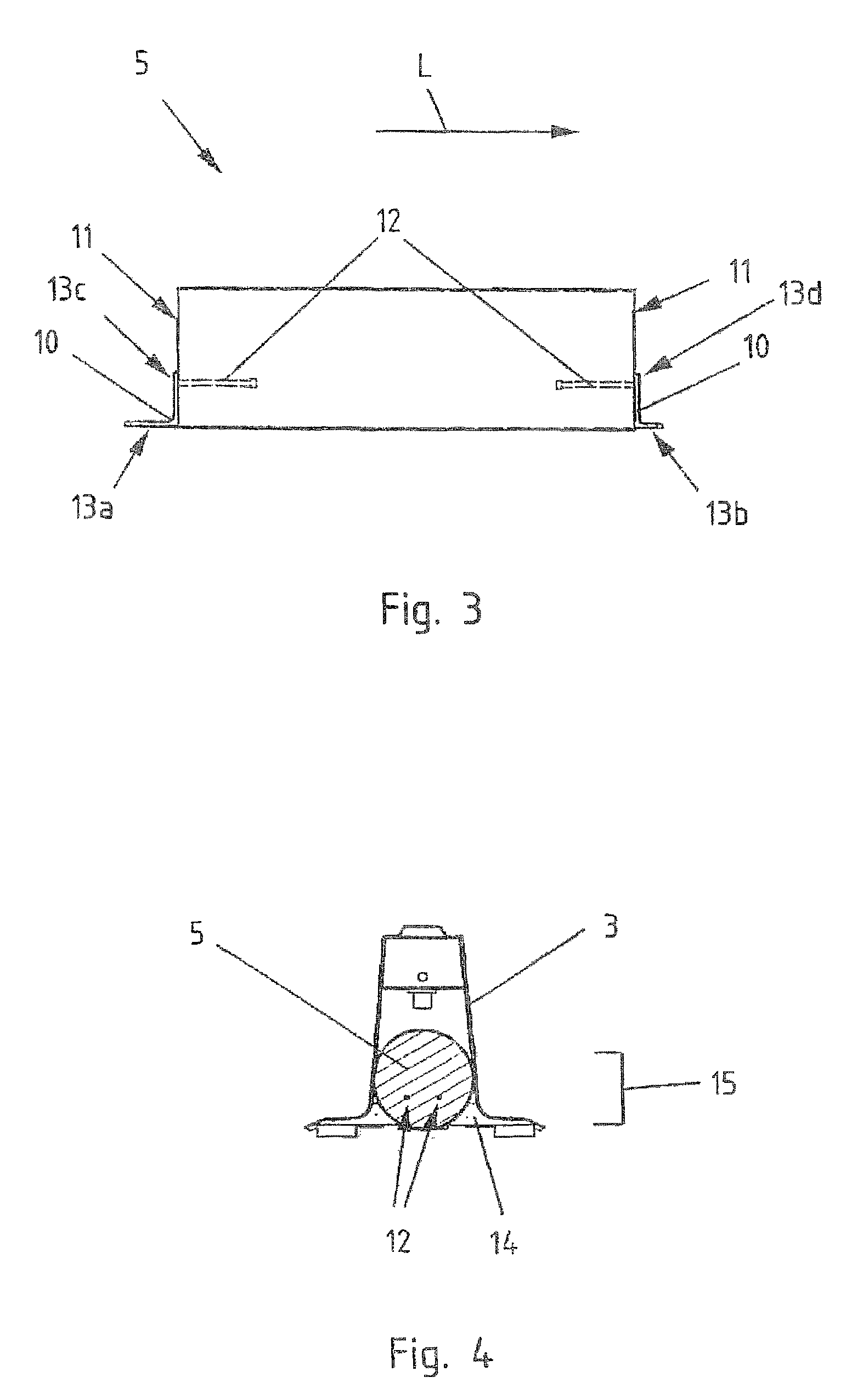
[0044]FIG. 2 shows a weighting body 5 for the fixation in a base body 3 of a vehicle restraint system 1. The weighting body 5 is constructed as follows; it is surrounded by a outer casing 6 which is filled with a curable filler 7. Preferably, the outer casing 6 is a plastic tube, and the curable f...


PUM


Abstract

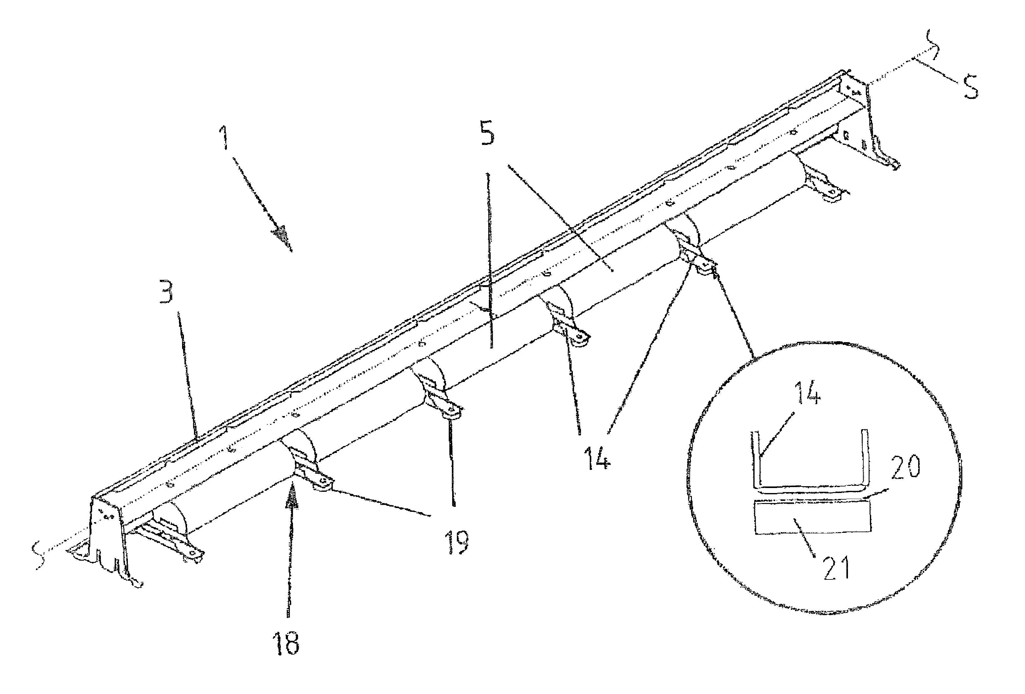
The present invention relates to a vehicle restraint system (1) for delimiting roadways, including base bodies (3) that can be detachably coupled to each other, wherein the base bodies (3) can be placed on a road surface (4) and have at least one weighting body (5). The weighting bodies (5) are formed by a outer casing (6), which is filled with a curable filler (7). Provided on the weighting bodies (5) are fasteners (8) which project out in relation to the weighting body (5), wherein the weighting bodies (5) can be fastened in the base body (3) by means of the fasteners. The vehicle restraint system (1) stands on the road surface (4) by means of support feet (19). The support feet (19) include a main body (20) and an elastomer body (21).

Description

CROSS-REFERENCES TO RELATED APPLICATIONS[0001]This application is the U.S. National Stage of International Application No. PCT / DE2010 / 001196, filed Oct. 12, 2010, which designated the United States and has been published as International Publication No. WO 2011 / 047659 and which claims the priority of German Patent Application, Serial No. 10 2009 050 266.1, filed Oct. 21, 2009, pursuant to 35 U.S.C. 119(a)-(d).BACKGROUND OF THE INVENTION[0002]The invention relates to a vehicle restraint system for delimiting roadways, including base bodies that can be detachably coupled to one another, wherein the base bodies can be placed on a road surface and have at least one weighting body.[0003]Vehicle restraint systems for delimiting roadways are known from the prior art. DE 200 03 791 U1 discloses a mobile protective steel wall for delimiting roadways made of individual wall segments which can be arranged end-to-end. Every wall segment has crash barriers arranged in parallel to the roadway and...

Claims


Application Information

Patent Timeline
IPC IPC(8): E01F15/00E01F15/08
CPCE01F15/085
Inventor VON LINSINGEN-HEINTZMANN, BARBARALASS, HORSTKLEIN, WALTERHEIMANN, WERNER
Owner BOCHUMER EISENHUTTE HEINTZMANN GMBH & CO BAU UND BET KG
Learn More