
Control panel including a resistive-type backlit key

a control panel and resistive technology, applied in the field of resistive backlit keys, can solve the problem of intransposable backlighting types, and achieve the effects of reducing integration costs, facilitating assembly operations, and more varied fascia styles

Active Publication Date: 2015-01-06
APTIV TECH LTD
View PDF7 Cites 5 Cited by
  • Summary
  • Abstract
  • Description
  • Claims
  • Application Information

AI Technical Summary

Benefits of technology

[0007]The present invention is intended to propose a simple, effective, and economical solution to allow the backlighting of a symbol situated on the resistive key, in the tactile pressure detection zone.
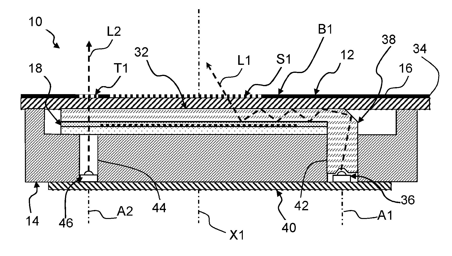
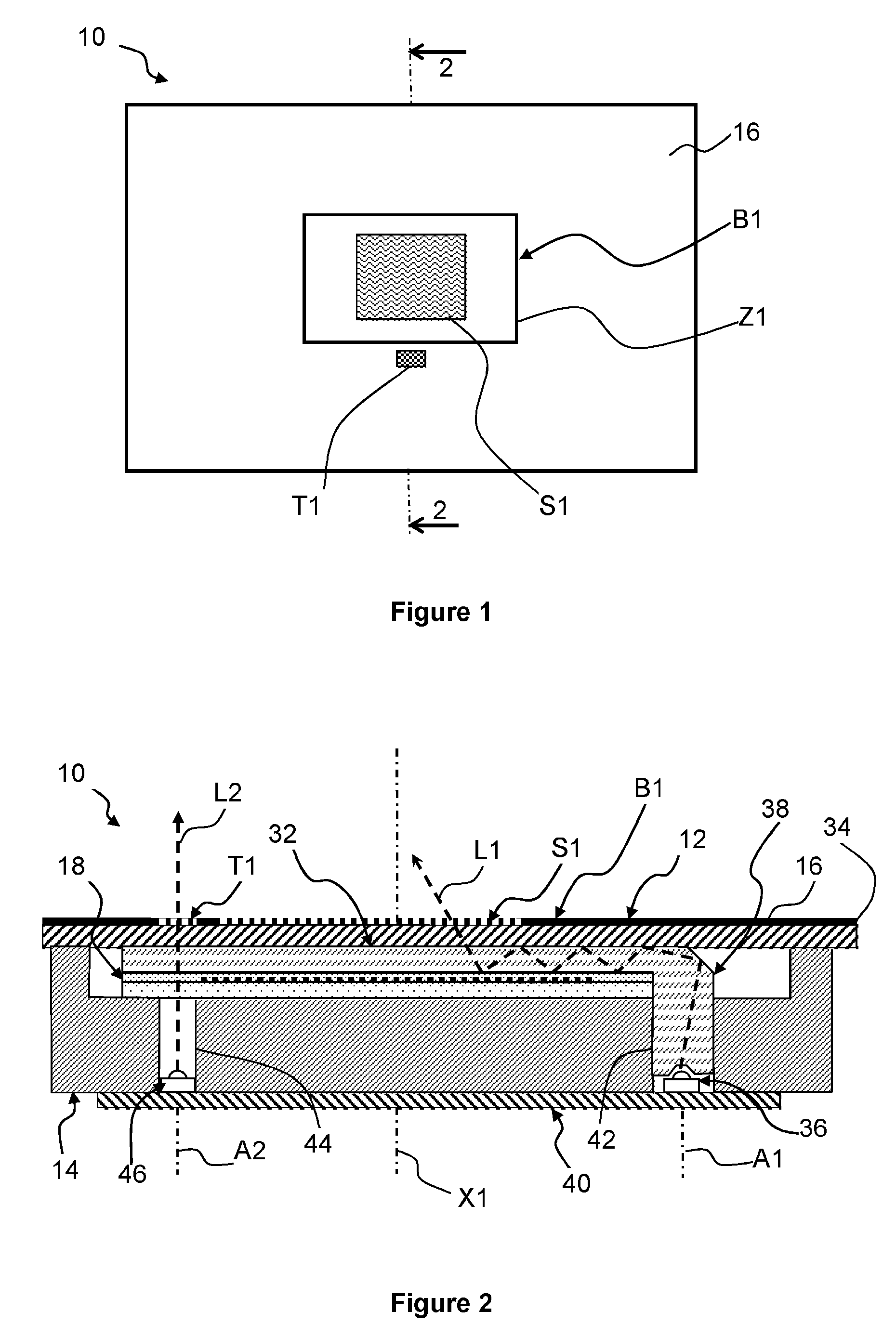
[0009]The invention allows a control panel to be obtained with backlit resistive keys in a small size and using a minimum of pieces which facilitates the assembly operations, allows more varied fascia styles, and reduces the integration costs. It permits the use of a force sensor such as a resistive sensor of FSR (Force Sensing Resistor) type without having to use transparent inks, unsuitable for motor vehicle applications, for the conductive tracks while guaranteeing good reliability of the control panel. Due to the invention the zone to be illuminated can be extended if required over the whole of the surface opposite the force sensor which offers greater freedom of definition of the pictograms of the control panel both with regard to the informative content and to the style

Problems solved by technology

This type of backlighting is not transposable to the case of a control panel with a resistive key due to the presence of the force sensor under the pressure zone behind the cover.

Method used


Image

  • Control panel including a resistive-type backlit key
  • Control panel including a resistive-type backlit key
  • Control panel including a resistive-type backlit key

Examples


Embodiment Construction

[0016]In the remainder of the description, identical or similar elements can be designated by identical references.

[0017]FIGS. 1 and 2 show a control panel 10 for a motor vehicle dashboard made in accordance with the teachings of the invention. The control panel 10 includes a cover 12 the outside surface 16 of which is provided with a detection zone Z1 of a tactile pressure forming a control button B1, or resistive key.

[0018]In the remainder of the description, an axial orientation will be used in non-limiting manner along an axis X1 substantially at right-angles to the general plane of the cover 12, orientated from the front towards the rear, which generally corresponds to an orientation from top to bottom considering FIG. 2.

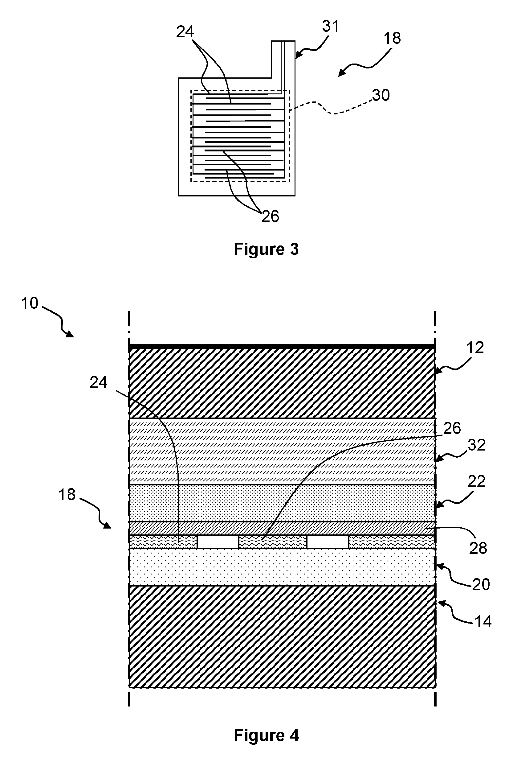
[0019]The control button B1 includes a force sensor 18 which is mounted between the cover 12 and a support 14 fixed to the back of the cover 12. The force sensor 18 is arranged axially facing the tactile pressure detection zone Z1, in order to allow the detecti...


PUM


Abstract

A control panel including a cover which is provided with at least one tactile pressure detection zone forming a control button, in which a force sensor is arranged between the cover and a support, behind the detection zone, in which a spacer made of elastically compressible material is mounted between the force sensor and the cover so as to take up the mechanical plays between the force sensor and the cover, characterized by the fact that the spacer is at least partially translucent and by the fact that the control panel includes at least one main light source and a light collector which permits injection of the light produced by the said main light source into the thickness of the spacer so that the spacer produces a backlighting beam directed towards a zone to be illuminated of the detection zone.

Description

CROSS-REFERENCE TO RELATED APPLICATION[0001]This application claims the benefit under 35 U.S.C. §371 of published PCT Patent Application Number PCT / EP 2012 / 061080, filed Jun. 12, 2012, claiming priority to French patent application number FR1155531 filed on Jun. 23, 2011, and published as WO2012 / 175369 on Dec. 27, 2012, the entire contents of which is hereby incorporated by reference herein.TECHNICAL FIELD OF INVENTION[0002]The present invention relates to a control panel, particularly for a motor vehicle, including a resistive backlit key.BACKGROUND OF INVENTION[0003]Generally, the control buttons used in a motor vehicle are of the push-button type, which is to say that they include an electrical switching device actuated by a mechanical control part. Each button, due to its dedicated kinematics, is individually visible on the fascia and this in a visual and tactile manner. To allow correct identification of the functions associated with each control button, it is known to provide ...

Claims


Application Information

Patent Timeline
Patent Type & Authority Patents(United States)
IPC IPC(8): G01D11/28B60K37/06H03K17/96
CPCB60K37/06H03K17/9625B60K2350/1036B60K2350/2008B60K2350/2034B60K2350/2039H03K2217/96042B60K2370/1446B60K2370/188B60K2370/331B60K2370/34
Inventor GEYL, LAURENTJANY, ERIC
Owner APTIV TECH LTD
Learn More