
Gas-discharge lamp replacement with passive cooling

a technology of passive cooling and discharge lamps, which is applied in the direction of gas-filled discharge tubes, energy-saving control techniques, electric circuit arrangements, etc., can solve the problems of limited new ballasts for mercury-vapor type of luminaires, low cri, and energy inefficiency. , to achieve the effect of reducing the cost of ligh

Active Publication Date: 2015-01-06
EXPRESS IMAGING SYST
View PDF229 Cites 34 Cited by
  • Summary
  • Abstract
  • Description
  • Claims
  • Application Information

AI Technical Summary

Benefits of technology

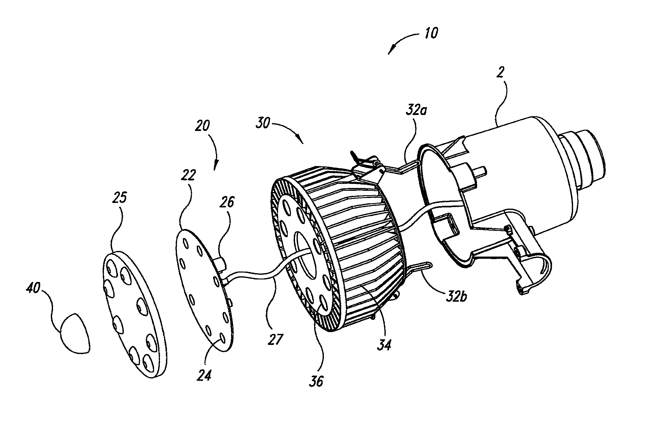
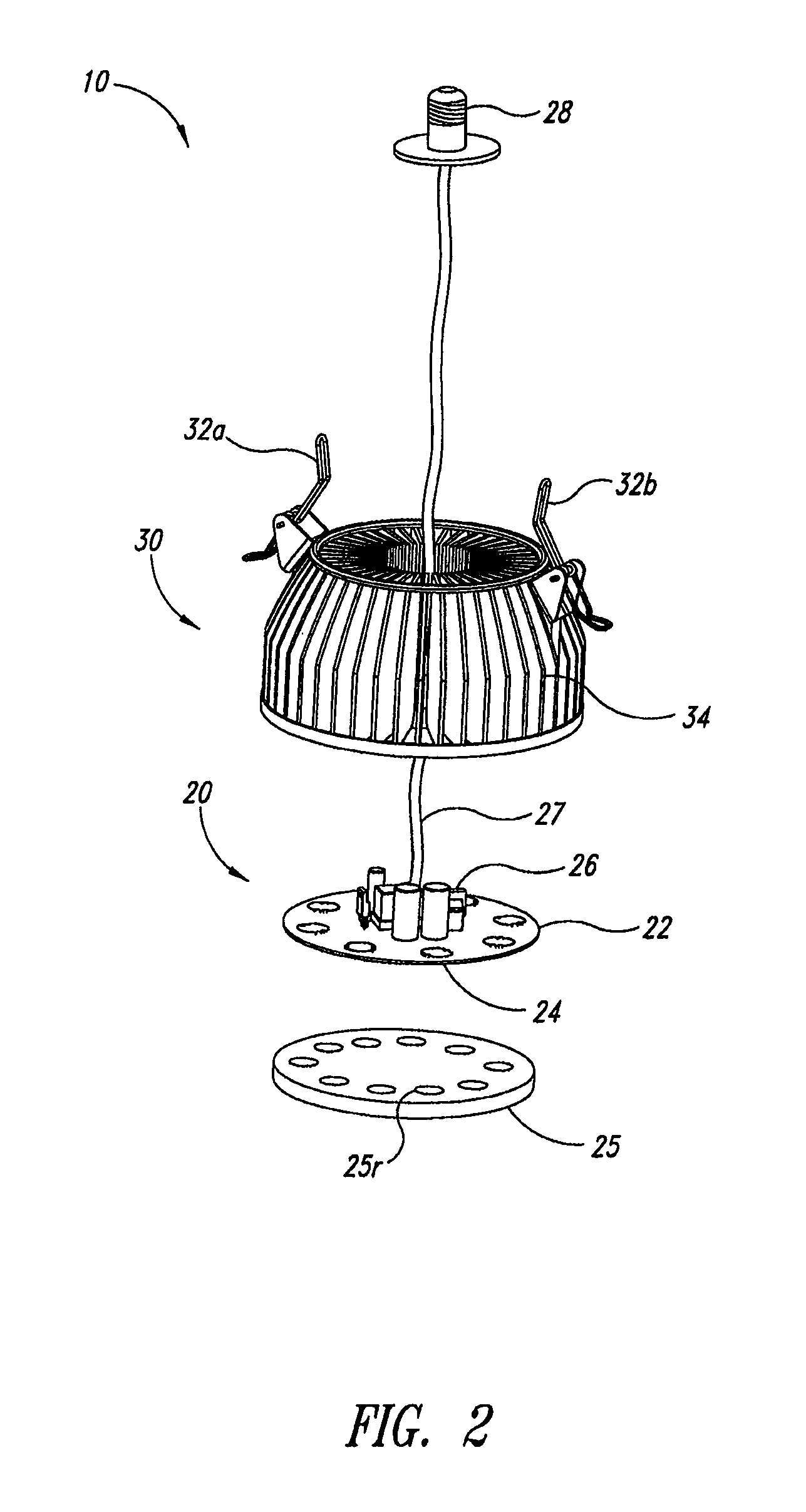
The patent describes an illumination device that includes a solid-state lighting device and a heat sink. The heat sink is designed to be attached to a fixture that is designed to receive a gas-discharge lamp. The heat sink is conductively thermally coupled to the solid-state lighting device to dissipate the heat generated by the device. The heat sink may have a plurality of fins that provide a large surface area for heat transfer. The device may also include an electronic ballast to regulate the power supplied to the solid-state lighting device. The device may also include a sensor switch that controls the operation of the solid-state lighting device based on the sensed ambient characteristic. The heat sink may be detachably mounted on the fixture that is designed to receive a gas-discharge lamp. The device may also include a control device that controls the operation of the lighting device based on motion or heat detection. The technical effect of the patent is to provide an efficient and effective illumination device that utilizes solid-state lighting technology and a heat sink for improved heat dissipation.

Problems solved by technology

As a result, new ballasts for mercury-vapor type of luminaires are limited to the quantity of ballasts still existing in the inventory of manufacturers, distributors, and retail sales stores.
One reason for banning the manufacturing and importation of mercury-vapor lamp ballasts was that the combination of mercury-vapor ballasts and mercury-vapor bulbs results in energy inefficiency as well as a very low power factor.
Light with a low CRI is less useful because illuminated surfaces are not all perceived as their true color.
Light with a low CRI is also less pleasing to the eye, and less useful for discrimination of an illuminated scene.
The long startup time prohibits the effective use of motion-detecting sensors to automatically turn mercury-vapor luminaires ON when people, animals or other objects are present.
This is a very wasteful solution to the warm-up time problem which consumes large amounts of energy when no light is needed.
A mercury-vapor lamp typically has much higher energy consumption during the warm-up time than during normal operation.
This can require expensive overdesign of the electrical wiring, especially when multiple mercury-vapor lamps may turn ON at the same time.
This light and the energy consumed to produce such light are wasted because the escaping light is not directed toward the areas the luminaires are intended to illuminate.
For example, such light pollutes the sky, causing problems for astronomers and others who wish to view the night sky.
Furthermore, mercury is a very toxic metal that contaminates landfills and water supplies when not disposed of properly, or when a mercury-vapor lamp is accidentally broken.
Consequently, mercury-vapor lamps are expensive and troublesome to dispose of at end of life.
High-pressure sodium-vapor lamps are somewhat more energy efficient than mercury-vapor lamps, but still suffer from poor CRI and also contain mercury.
Metal halide lamps are not commonly available to work with mercury-vapor lamp ballasts, and typically require a higher ignition voltage to start.
Neither corrects for the poor optical design of the security light luminaires.
Both alternative types of lamps have poor power factors.
Thus, none of these alternative gas-discharge lamps can serve as an ideal replacement of mercury-vapor lamps to fully address the aforementioned problems associated with mercury-vapor lamps.
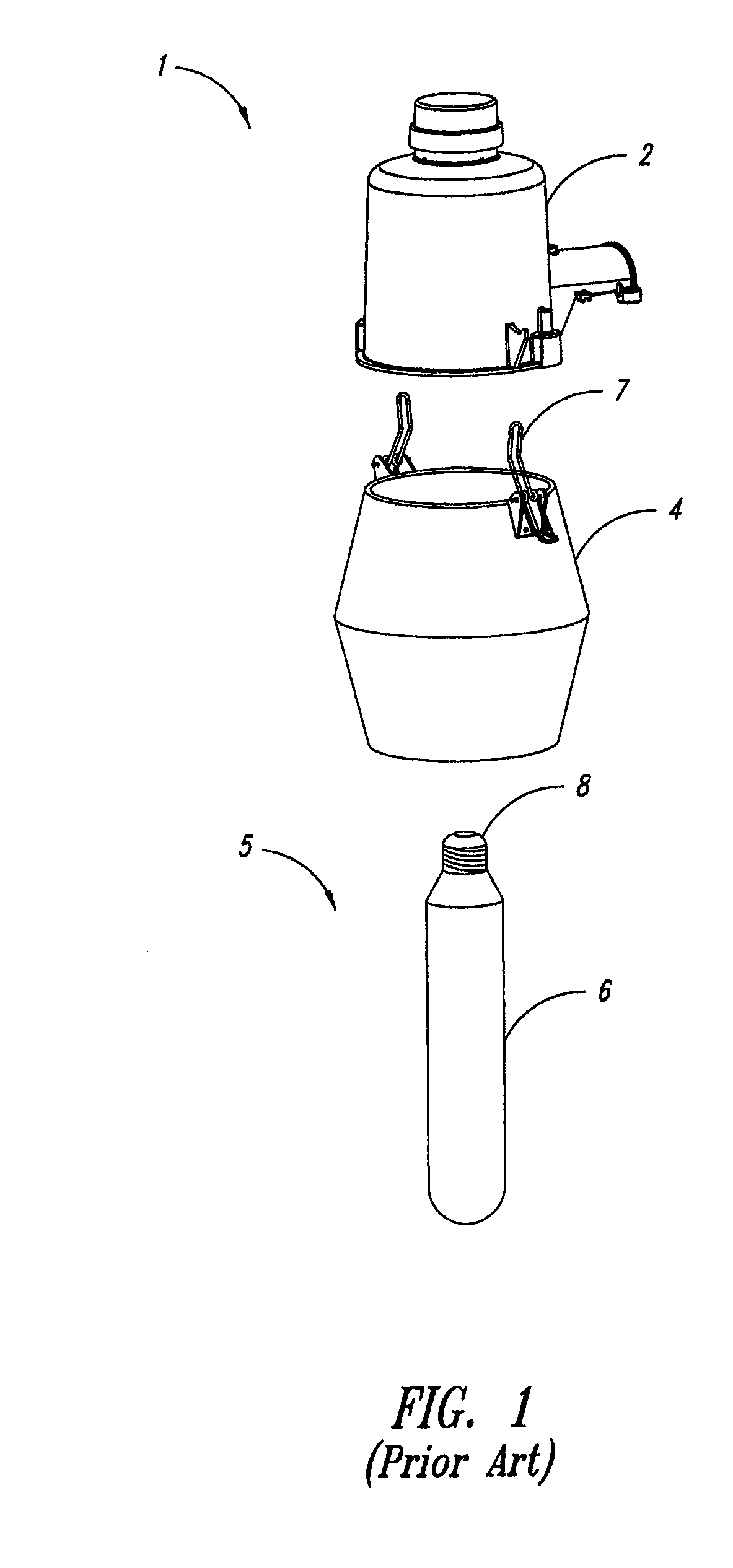
Such an active cooling system, however, constitutes additional costs to the replacement lamp and requires an unobstructed air path to operate.
On the other hand, LED lamps without cooling have been shown to have shorter service life due to the high temperatures that result from operating the LED lamp in the enclosed space of the luminaire's cover / refractor.

Method used


Image

  • Gas-discharge lamp replacement with passive cooling
  • Gas-discharge lamp replacement with passive cooling
  • Gas-discharge lamp replacement with passive cooling

Examples


Embodiment Construction

[0030]In the following description, certain specific details are set forth in order to provide a thorough understanding of various disclosed embodiments. However, one skilled in the relevant art will recognize that embodiments may be practiced without one or more of these specific details, or with other methods, components, materials, etc. In other instances, well-known structures associated with lighting fixtures, luminaires and / or LED lighting have not been shown or described in detail to avoid unnecessarily obscuring descriptions of the embodiments.

[0031]Unless the context requires otherwise, throughout the specification and claims which follow, the word “comprise” and variations thereof, such as, “comprises” and “comprising” are to be construed in an open, inclusive sense that is as “including, but not limited to.”

[0032]Reference throughout this specification to “one embodiment” or “an embodiment” means that a particular feature, structure or characteristic described in connecti...


PUM


Abstract

An illumination device comprises a solid-state lighting device and a heat sink. The heat sink is configured to be attachable to a fixture for a gas-discharge lamp to retrofit existing gas-discharge fixtures. The heat sink is conductively thermally coupled to the solid-state lighting device to dissipate heat generated by the solid-state lighting device.

Description

CROSS REFERENCE TO RELATED APPLICATIONS[0001]This application claims benefit under 35 U.S.C. 119(e) of U.S. Provisional Patent Application Ser. No. 61 / 174,913, filed May 1, 2009 and entitled “GAS-DISCHARGE LAMP REPLACEMENT with passive cooling,” which is incorporated herein by reference in its entirety.BACKGROUND[0002]1. Technical Field[0003]This disclosure generally relates to illumination devices and more particularly to illumination devices to retrofit light fixtures as a replacement of gas-discharge lamps.[0004]2. Description of the Related Art[0005]Gas-discharge lamps are a family of artificial light sources that generate light by sending an electrical discharge through an ionized gas. Mercury-vapor lamps, a type of gas-discharge lamps and commonly referred to as “security lights”, use mercury in an excited state to produce light. The Energy Conservation Act of 2005 bans the manufacture and importation of mercury-vapor ballasts and luminaires. As a result, new ballasts for merc...

Claims


Application Information

Patent Timeline
Patent Type & Authority Patents(United States)
IPC IPC(8): F21V29/00F21K99/00F21V23/04F21Y101/02F21Y103/02H05B37/02H05B44/00
CPCH05B37/0227F21V23/04F21V29/2231F21K9/13F21V29/246H05B33/0803H05B33/0854F21V23/0442Y02B20/383F21Y2101/02F21Y2103/022Y10S362/80F21V23/0478F21V29/773F21V29/89F21K9/23F21Y2103/33F21Y2115/10H05B45/10Y02B20/30H05B47/13H05B45/385H05B47/125Y02B20/40F21V29/00
Inventor REED, WILLIAM G.RENN, JOHN O.
Owner EXPRESS IMAGING SYST
Learn More