Anti-corrosion structure for wire connecting portion

a technology of anti-corrosion structure and wire connection, which is applied in the direction of connection contact material, cable junction, cable termination, etc., can solve the problems of limiting the strength of the housing, affecting the service life of the housing, and affecting the service life of the connection portion, so as to prevent the electrolytic corrosion of the wire connection portion

Inactive Publication Date: 2015-01-06
SUMITOMO WIRING SYST LTD
View PDF28 Cites 20 Cited by
  • Summary
  • Abstract
  • Description
  • Claims
  • Application Information

AI Technical Summary

Benefits of technology

[0008]The present invention was developed based on the situation as described above and an object thereof is to prevent electrolytic corrosion of a wire connecting portion while permitting the interference of a sealing resin and the inner wall of a through hole.
[0010]If the wire connecting portion is partly exposed at the both front and rear end parts thereof due to the interference of the sealing resin with the inner wall of the through hole, interfaces between the sealing resin and the wire are exposed and water tends to enter the wire connecting portion through these interfaces. In this respect, according to the configuration of the present invention, a part (exposed portion) of the wire connecting portion is exposed in the intermediate part of the wire connecting portion and an interface between the sealing resin and the wire connecting portion is exposed at the exposed portion. However, since the sealing resin and the wire connecting portion are held in close contact with each other, water does not enter the wire connecting portion through this interface. Thus, electrolytic corrosion of the wire connecting portion can be prevented while the interference of the sealing resin and the inner wall of the through hole is permitted.

Problems solved by technology

Since the terminal is generally made of copper alloy in view of a problem in strength and the like, electrolytic corrosion is certainly a problem if the aluminum wire is used as described above.
However, in the above configuration, the housing is open upward and the wire connecting portion can be arranged while being displaced upward, but the sealing resin interferes with the inner wall of a through hole provided in the housing if the wire connecting portion is displaced upward in the case of accommodating the terminal into the through hole.
On the other hand, even if a clearance between the inner wall of the through hole and the sealing resin is enlarged by carving the inner wall of the through hole, there is a limit in terms of securing the strength of the housing.

Method used


Image

  • Anti-corrosion structure for wire connecting portion
  • Anti-corrosion structure for wire connecting portion
  • Anti-corrosion structure for wire connecting portion

Examples


first embodiment

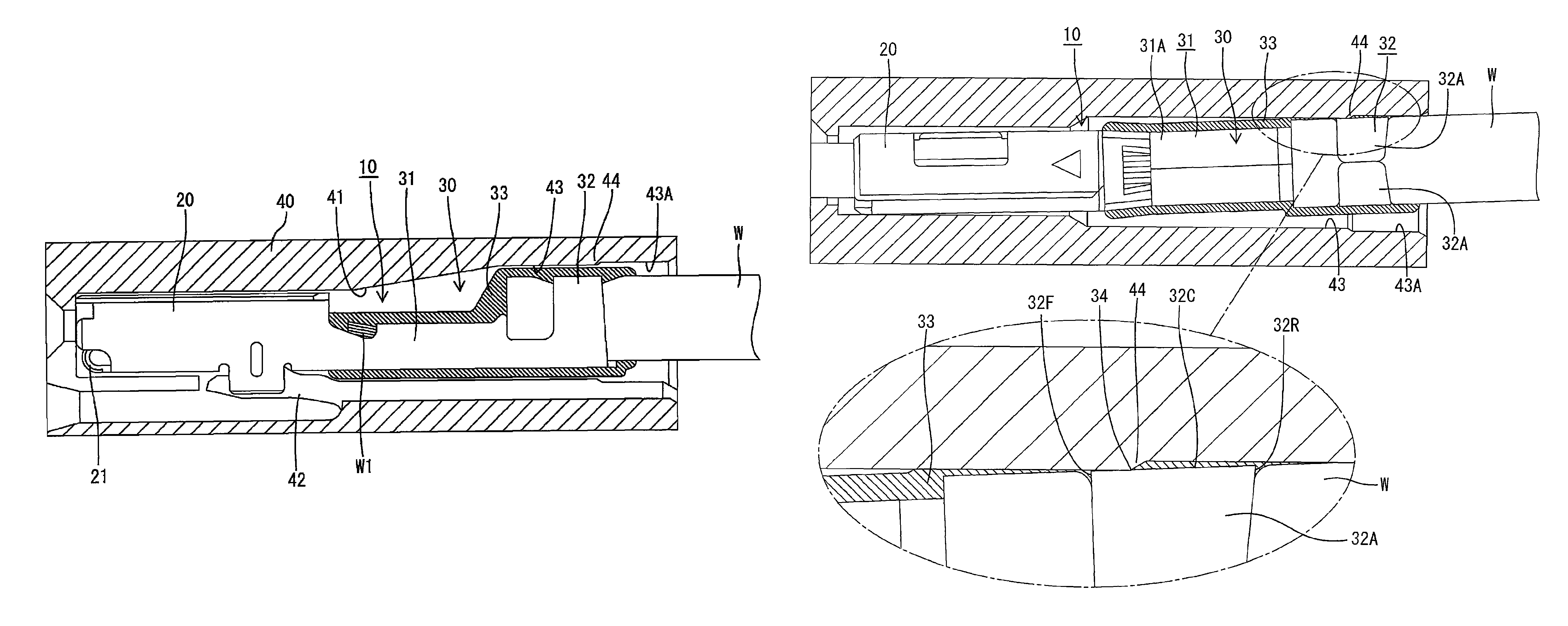
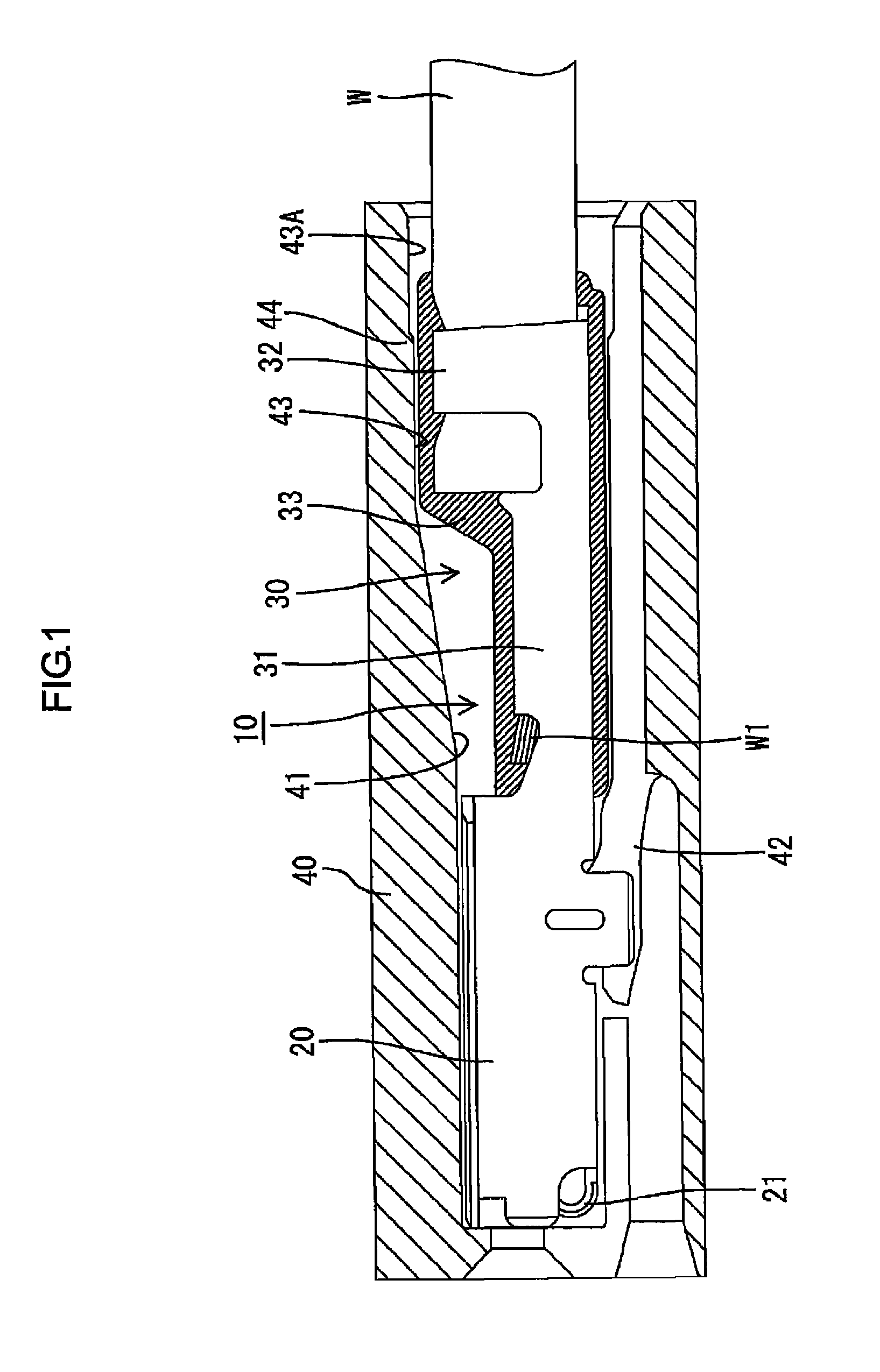
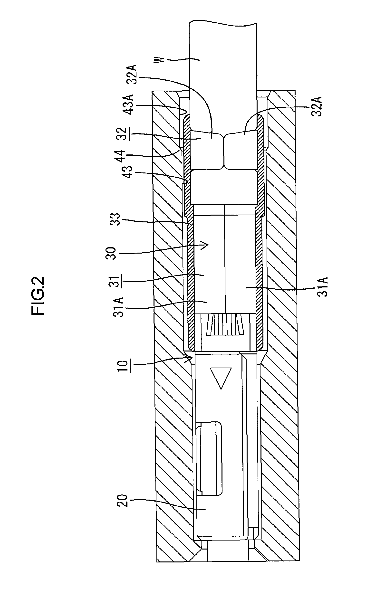
[0025]A first embodiment of the present invention is described in detail with reference to FIGS. 1 to 10. A terminal 10 in this embodiment is made of copper alloy and includes a terminal connecting portion 20 connectable to a male terminal (see FIG. 11) and a wire connecting portion 30 formed behind this terminal connecting portion 20. This terminal 10 is inserted and accommodated from behind into a through hole 41 formed to penetrate a housing 40 in forward and backward directions. A locking lance 42 extending forward in a cantilever manner is formed in the through hole 41. This locking lance 42 is engaged with the terminal 10, whereby the terminal 10 is held in the through hole 41 so as not to come out backward.

[0026]The terminal connecting portion 20 is in the form of a rectangular tube which is open forward and backward, and the male terminal is fittable thereinto through a front end opening thereof. Further, a resilient contact piece 21 is formed in the terminal connecting port...

second embodiment

[0038]Next, a second embodiment of the present invention is described with reference to FIGS. 11 to 14. In this embodiment, the terminal of the present invention is applied to a male terminal. A terminal 50 of this embodiment is connectable to a female terminal (see FIG. 1). The terminal 50 includes a tab portion 51 to be fitted into the female terminal. The tab portion 51 is in the form of a flat plate. The other configuration, functions and effects are the same as in the first embodiment and not repeatedly described.

[0039]FIG. 11 shows a state where a stepped part 62 formed on the inner wall of a through hole 61 of a housing 60 interferes with a sealing resin 53 sealing a wire connecting portion 52 of the terminal 50 with resin due to an upward swinging movement of an aluminum wire W at an advanced position. FIG. 12 shows a state where the stepped part 62 comes into line contact with an exposed portion 54 exposed on outer peripheral surfaces 52C of both barrel pieces 52A forming t...


PUM


Abstract

A terminal assembly includes a wire including a core made of metal and covered with a coating, a terminal including a wire connecting portion connected to an end portion of the wire, a sealing resin sealing the wire connecting portion, and a housing including a through hole with a front opening and a rear opening. The terminal is made of a different kind of metal from the core of the wire. The housing accommodates the terminal in the through hole. The wire connecting portion includes an exposed portion not covered with the sealing resin and unexposed portions covered with the sealing resin. The exposed portion is positioned between the unexposed portions in a front and rear direction, thereby protecting the wire connecting portion from electrolytic corrosion. The exposed portion is obtained after the sealing resin is worn by being rubbed against an inner wall of the through hole.

Description

BACKGROUND OF THE INVENTION[0001]1. Field of the Invention[0002]The present invention relates to an anti-corrosion structure for a wire connecting portion.[0003]2. Description of the Related Art[0004]In recent years, aluminum wires have been used for weight saving and other purposes also in the field of automotive wiring harnesses and the like. An aluminum wire is, for example, structured by covering a core formed by twisting a plurality of aluminum strands with a coating. In the case of forming a wiring harness, the aluminum wire is connected to a wire connecting portion of a terminal. This wire connecting portion is specifically composed of a wire barrel portion to be crimped and connected to an end of the core exposed by stripping the coating at an end of the aluminum wire and an insulation barrel portion to be crimped and connected to an end of the remaining coating.[0005]In electrically conductively connecting a wire to a terminal, if a core of the wire and the terminal are mad...

Claims


Application Information

Patent Timeline
Patent Type & Authority Patents(United States)
IPC IPC(8): H01R4/00H01R4/18H01R4/62H01R4/70H02G15/04
CPCH02G15/04H01R4/70H01R4/185H01R4/62
Inventor TANIKAWA, NAOTAKAKATO, HIROKOKOBAYASHI, KAZUMASAKOJIMA, EIJIKOBAYASHI, HIROSHI
Owner SUMITOMO WIRING SYST LTD
Why Eureka
Try Eureka