Printer with front and back imaging systems

Inactive Publication Date: 2015-01-13
EASTMAN KODAK CO
View PDF7 Cites 9 Cited by
  • Summary
  • Abstract
  • Description
  • Claims
  • Application Information

AI Technical Summary

Benefits of technology

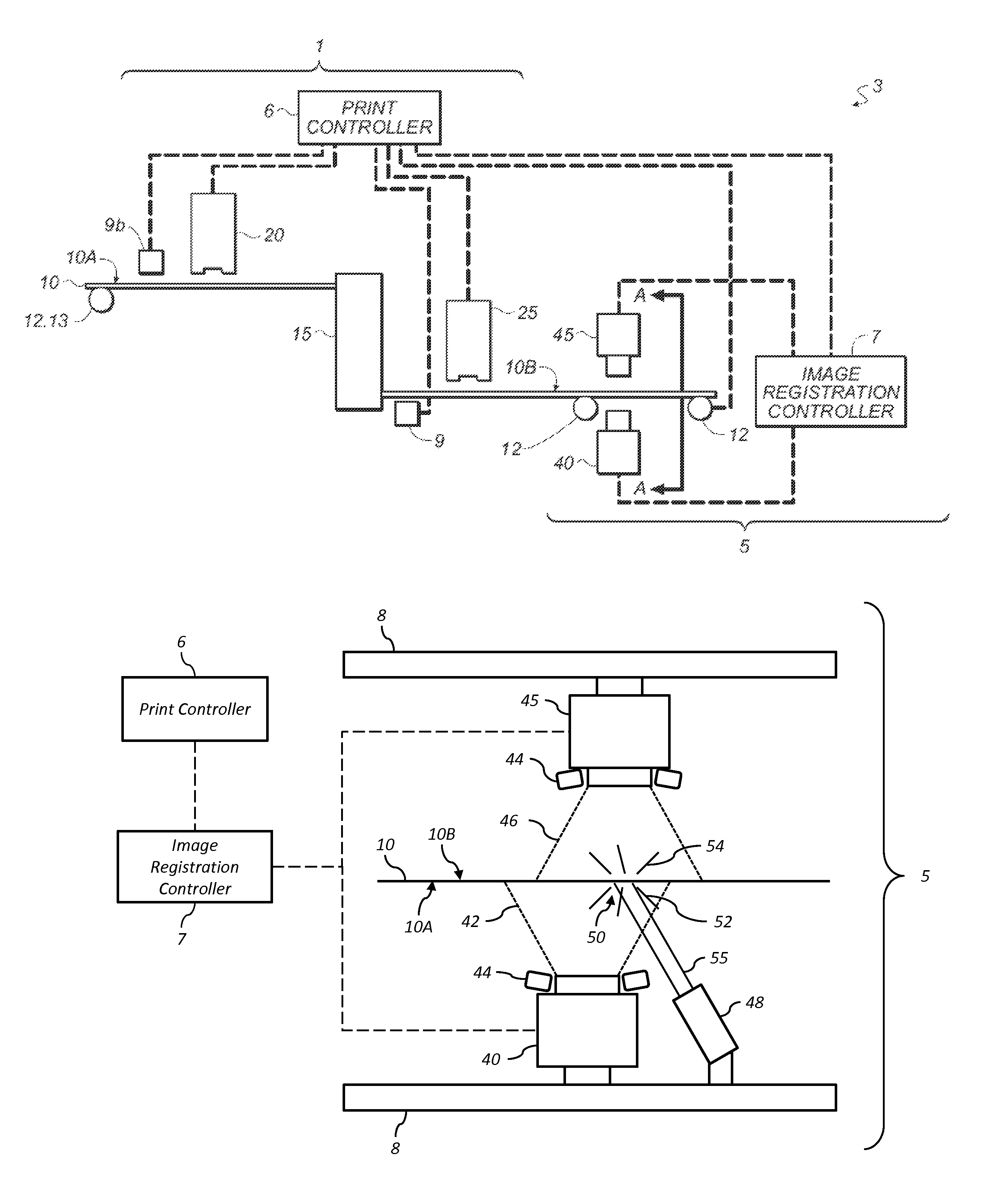
[0024]This invention has the advantage that the imaging systems can be aligned without the need for using any printed registration marks.
[0025]It has the additional advantage that the position of the illumination pattern is independent of the position of the receiver

Problems solved by technology

As ink is applied to the receiver medium by the printheads of the printing system, it is absorbed by the receiver medium, and typically causes the receiver medium to expand.
Expansion of the receiver medium often adversely affects the alignment of the receiver medium relative to the media transport of the printing system, which can lead to a reduction in print quality.
Additionally, the absorption of ink by the receiver medium, often in

Method used


Image

  • Printer with front and back imaging systems
  • Printer with front and back imaging systems
  • Printer with front and back imaging systems

Examples


Example

[0042]It is to be understood that the attached drawings are for purposes of illustrating the concepts of the invention and may not be to scale.

DETAILED DESCRIPTION OF THE INVENTION

[0043]In the following description, some embodiments of the present invention will be described in terms that would ordinarily be implemented as software programs. Those skilled in the art will readily recognize that the equivalent of such software may also be constructed in hardware. Because image manipulation algorithms and systems are well known, the present description will be directed in particular to algorithms and systems forming part of, or cooperating more directly with, the method in accordance with the present invention. Other aspects of such algorithms and systems, together with hardware and software for producing and otherwise processing the image signals involved therewith, not specifically shown or described herein may be selected from such systems, algorithms, components, and elements known...


PUM


Abstract

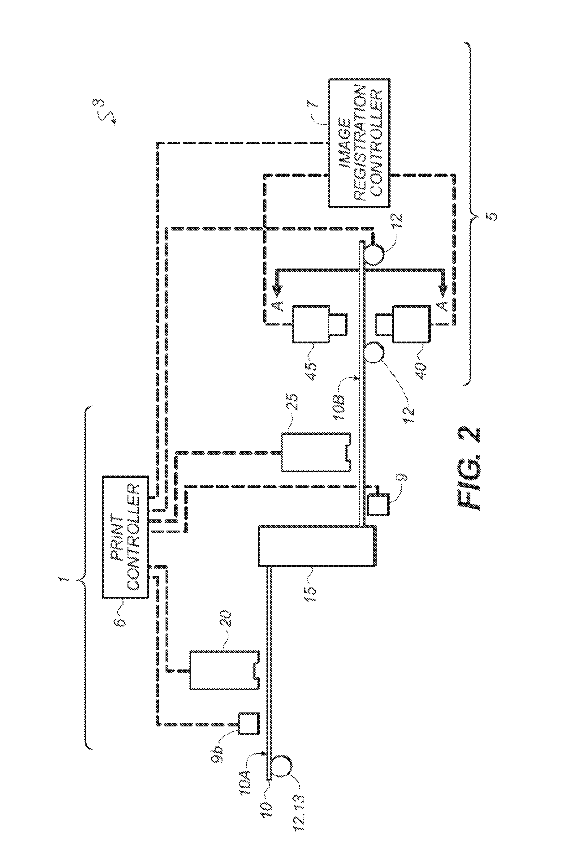
A printing system includes a plurality of imaging systems for capturing images of a receiver medium. An illumination system illuminates the receiver medium with an illumination pattern, thereby providing a reflected illumination pattern and a transmitted illumination pattern. A first imaging system is positioned to capture a first image of a first side of the receiver medium including the reflected illumination pattern, and a second imaging system is positioned to capture a second image of an opposing second side of the receiver medium including the transmitted illumination pattern. The first and second images are analyzed to determine a relative position of the reflected illumination pattern in the first image and the transmitted illumination pattern in the second image. Imaging system alignment parameters for use in aligning images captured with the first and second imaging systems are determined responsive to the determined relative position.

Description

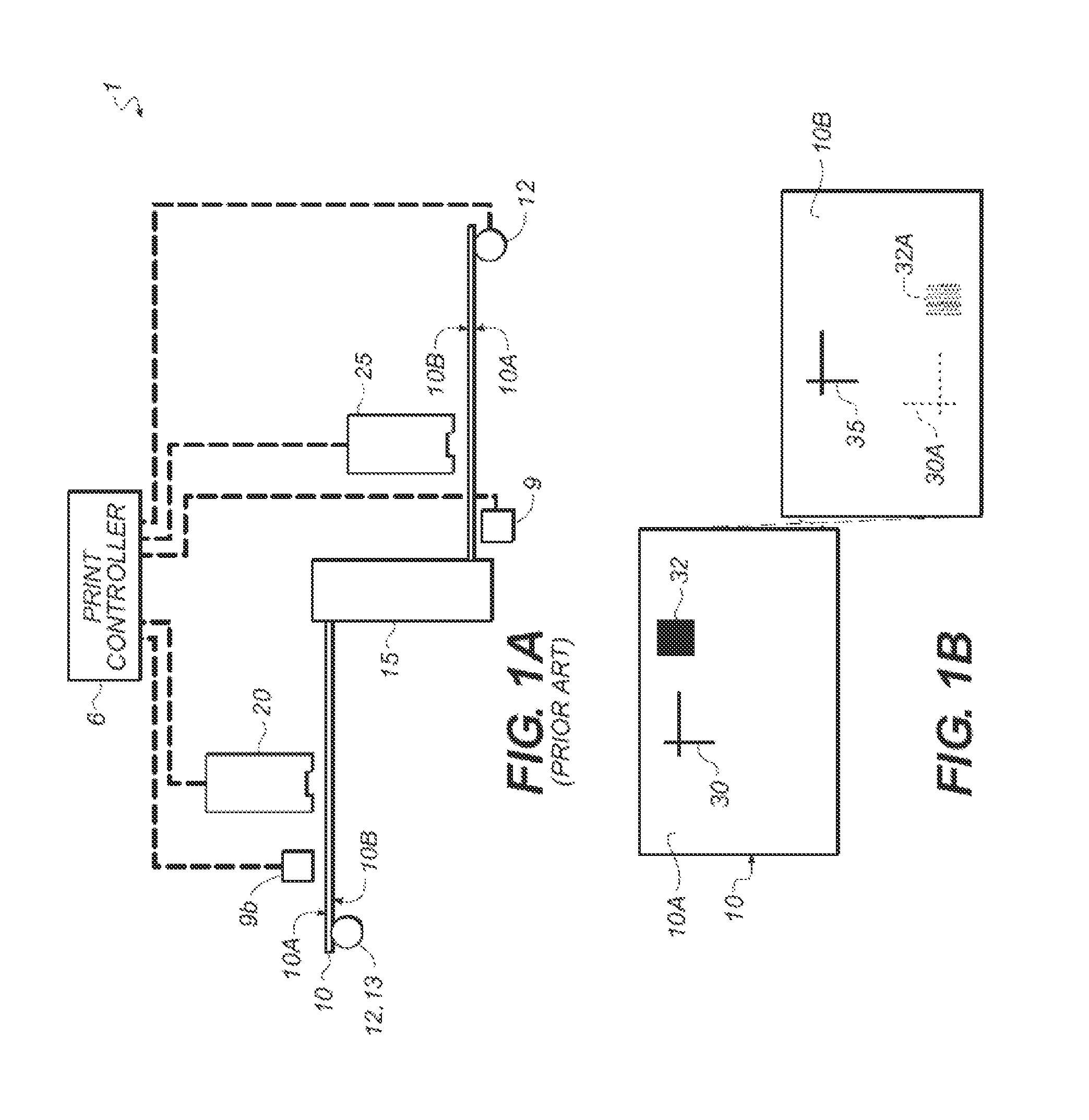
CROSS REFERENCE TO RELATED APPLICATIONS[0001]Reference is made to commonly assigned, co-pending U.S. patent application Ser. No. 14 / 064,408, entitled: “Imaging module with aligned imaging systems”, by Duke et al.; and to commonly assigned, co-pending U.S. patent application Ser. No. 14 / 064,443, entitled: “Method for aligning imaging systems”, by Duke et al., each of which is incorporated herein by reference.FIELD OF THE INVENTION[0002]This invention relates generally to the field of digitally controlled printing systems, and in particular to the registration of imaging systems used in the alignment of patterns, for example, images or text, printed by these systems.BACKGROUND OF THE INVENTION[0003]Many printing systems are configured to print on both a front side and a back side of a receiver medium. Typically, a pattern (e.g., an image or text) is printed on the front side of the receiver medium using one portion of the printing system. After transportation of the receiver medium to...

Claims


Application Information

Patent Timeline
IPC IPC(8): H04N1/034B41J29/00
CPCB41J29/00B41F13/025B41J3/60B41J11/008B41J11/46B65H9/20B65H7/14B65H9/00B65H2553/42
Inventor DUKE, RONALD J.KATERBERG, JAMES ALAN
Owner EASTMAN KODAK CO
Why Eureka
Try Eureka