
Control of a brushless motor

a brushless motor and control technology, applied in current controllers, electronic commutators, synchronous motor starters, etc., can solve the problems of requiring a faster and more expensive controller, and achieve the effect of simple and cheap controller, simplified control, and simplified motor control

Inactive Publication Date: 2015-01-13
DYSON TECH LTD
View PDF210 Cites 16 Cited by
  • Summary
  • Abstract
  • Description
  • Claims
  • Application Information

AI Technical Summary

Benefits of technology

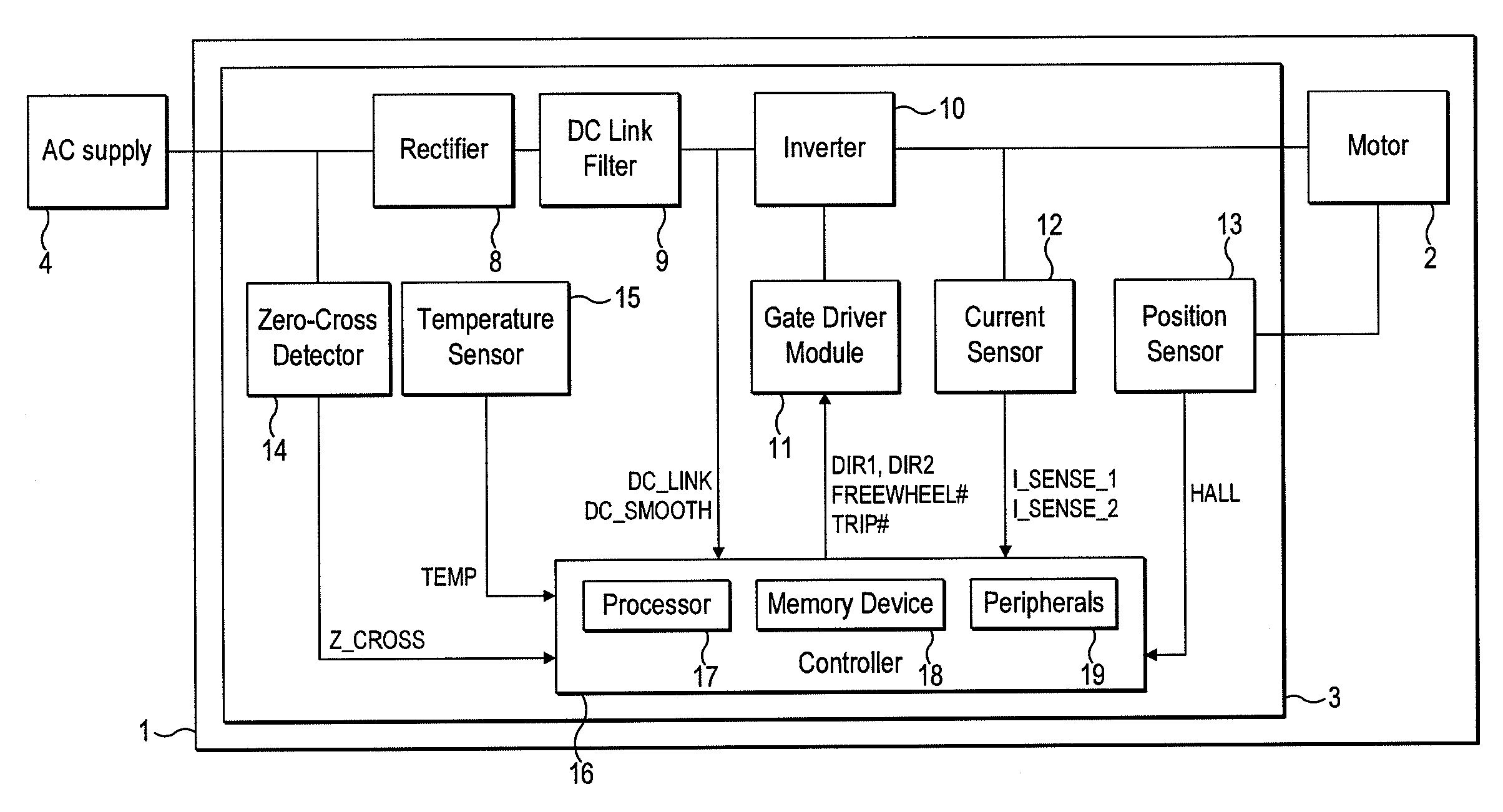
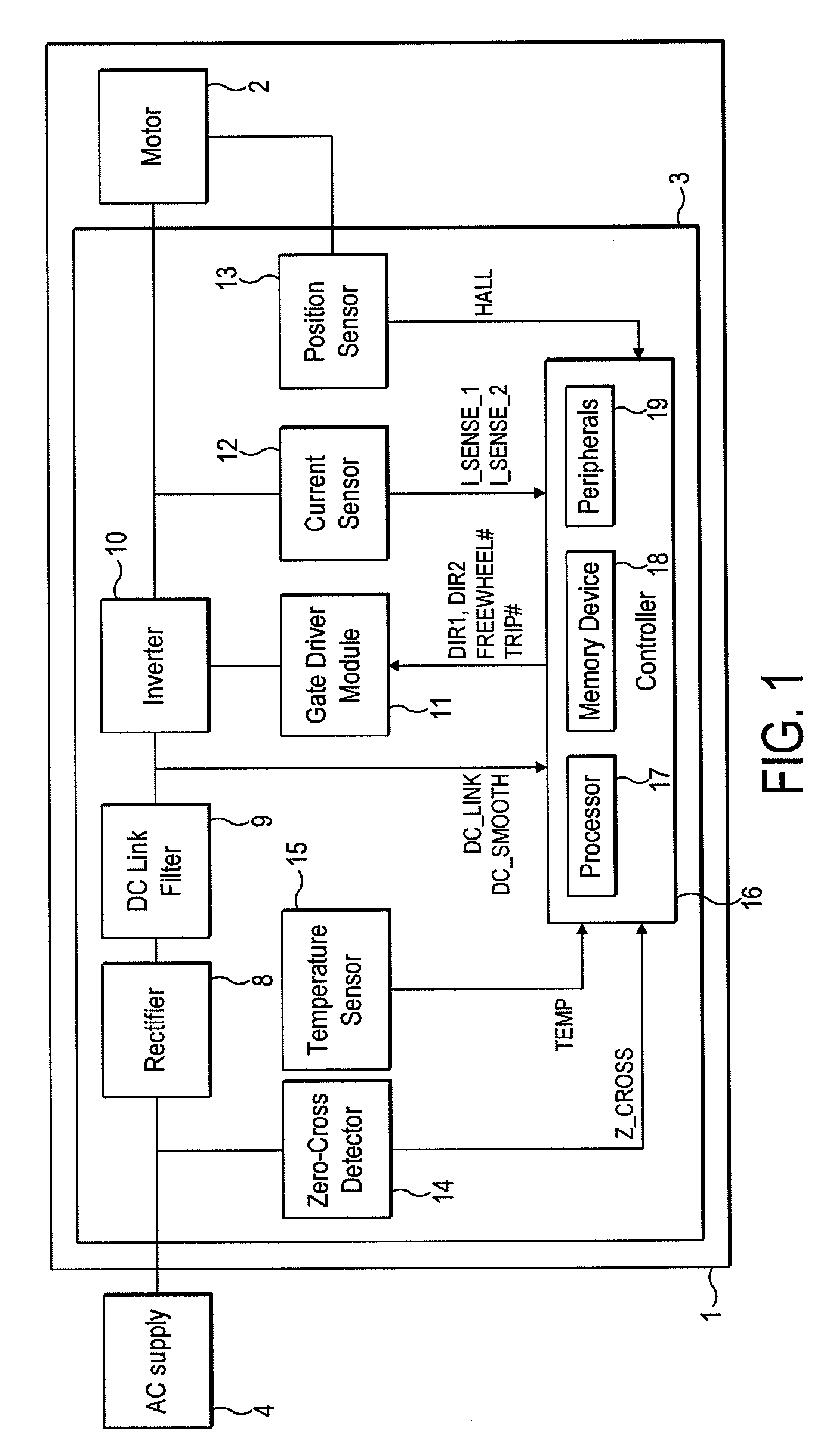
[0006]The freewheel period is therefore updated at regular intervals irrespective of motor speed. Moreover, the freewheel period is updated regularly without the need for a dedicated timer. By updating the freewheel period in response to zero-crossings in the alternating voltage, control of the motor is relatively simple and thus a relatively simple and cheap controller may be used to implement the method.
[0019]The controller may use the same freewheel period for each electrical half-cycle of the motor spanning one half-cycle of the alternating voltage. This then simplifies the control implemented by the controller and thus a relatively simple and cheap controller may be used.

Problems solved by technology

However, the control system must then calculate the corresponding freewheel time on-the-fly, which requires a faster and more expensive controller.

Method used


Image

  • Control of a brushless motor
  • Control of a brushless motor
  • Control of a brushless motor

Examples


specific example

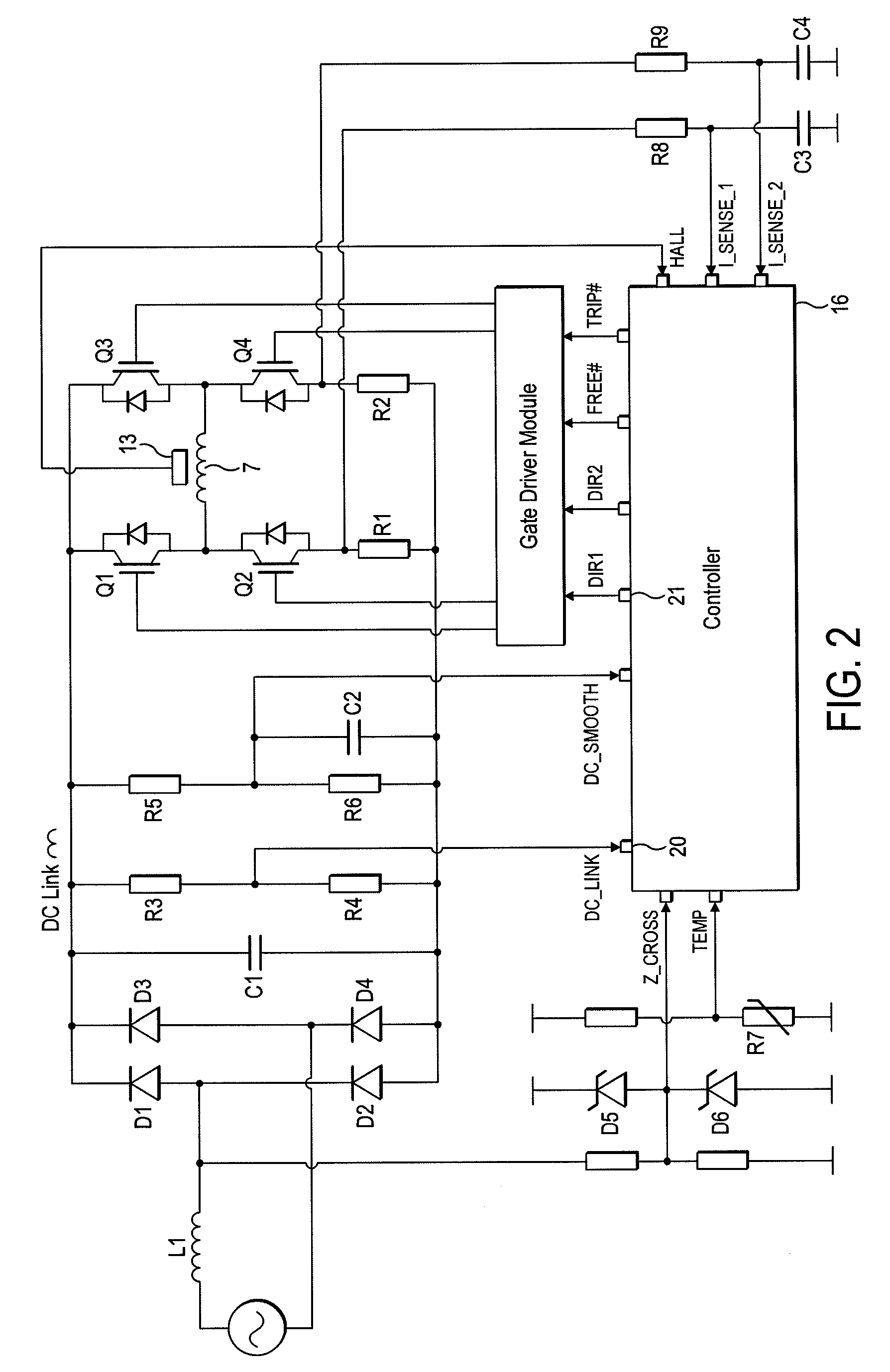
[0242]A particular embodiment of the motor system 1 will now be described by way of example only. Values for various hardware components of the motor system 1 are detailed in FIG. 19, while FIG. 20 lists various constants and thresholds employed by the controller 16. FIGS. 21 and 22 detail the flux-linkage characteristics of the link inductor L1 and the motor 2.

[0243]As illustrated in FIG. 23, the motor system 1 has seven modes of operation: Fault, Initialization, Stationary, Low-Speed Acceleration, Mid-Speed Acceleration, High-Speed Acceleration, and Running. Accordingly, in comparison to that previously described and illustrated in FIG. 8, the motor system 1 has one additional mode of operation.

[0244]Fault, Initialization, Stationary and Low-Speed Acceleration Modes are unchanged from that previously described. Mid-Speed Acceleration Mode corresponds to the previously-described High-Speed Acceleration Mode. Consequently, when operating in Mid-Speed Acceleration Mode, the controlle...


PUM


Abstract

A method of controlling a brushless motor that includes rectifying an alternating voltage to provide a rectified voltage, exciting a winding of the motor with the rectified voltage and freewheeling the winding when current in the winding exceeds a threshold. The winding is freewheeled for a freewheel period, which is updated in response to a zero-crossing in the alternating voltage. Additionally, a control system that implements the method, and a motor system that incorporates the control system.

Description

REFERENCE TO RELATED APPLICATIONS[0001]This application claims the priority of United Kingdom Application No. 1006397.2, filed Apr. 16, 2010, the entire contents of which are incorporated herein by reference.FIELD OF THE INVENTION[0002]The present invention relates to control of a brushless motor.BACKGROUND OF THE INVENTION[0003]A brushless motor generally includes a control system that controls the excitation of phase windings of the motor. The control system may employ a current control scheme in which a winding is excited until current in the winding exceeds a threshold. On exceeding the threshold, the control system freewheels the winding so as to allow current in the winding to decay. Freewheeling may continue until current in the winding decays to a lower threshold, at which point the winding is again excited. Alternatively, the control system may freewheel the winding for a fixed period of time, after which the winding is again excited.[0004]As the motor speed increases, the ...

Claims


Application Information

Patent Timeline
Patent Type & Authority Patents(United States)
IPC IPC(8): H02P6/00H02P29/02
CPCH02P6/002H02P29/028H02P2209/07H02P6/28H02P29/032H02P6/15H02P6/34H02P6/085
Inventor CHEN, YUCELIK, TUNCAYGREETHAM, STEPHEN
Owner DYSON TECH LTD
Learn More