
Unified management platform in a computer network

a technology of computer network and management platform, applied in the field of computer network and system management, can solve the problems of user performance degradation and even downtime, and the conventional approach to determining capacity bottlenecks is very laborious, and achieve the effect of reducing the time and cost of utilizing and maintaining, and optimizing the time for system administrators

Active Publication Date: 2015-01-13
QUEST SOFTWARE INC
View PDF117 Cites 9 Cited by
  • Summary
  • Abstract
  • Description
  • Claims
  • Application Information

AI Technical Summary

Benefits of technology

[0017]Yet another exemplary implementation of the present invention provides a GUI that facilitates predictive analysis of computing objects utilizing resources in a computer network by providing, for example, a slider user interface allowing a user to specify a time period within a range of time periods for predictive analyses. A slider can be displayed along with resource utilization information for the computing objects, so that a user can receive immediate feedback via the display while selectively manipulating the slider.
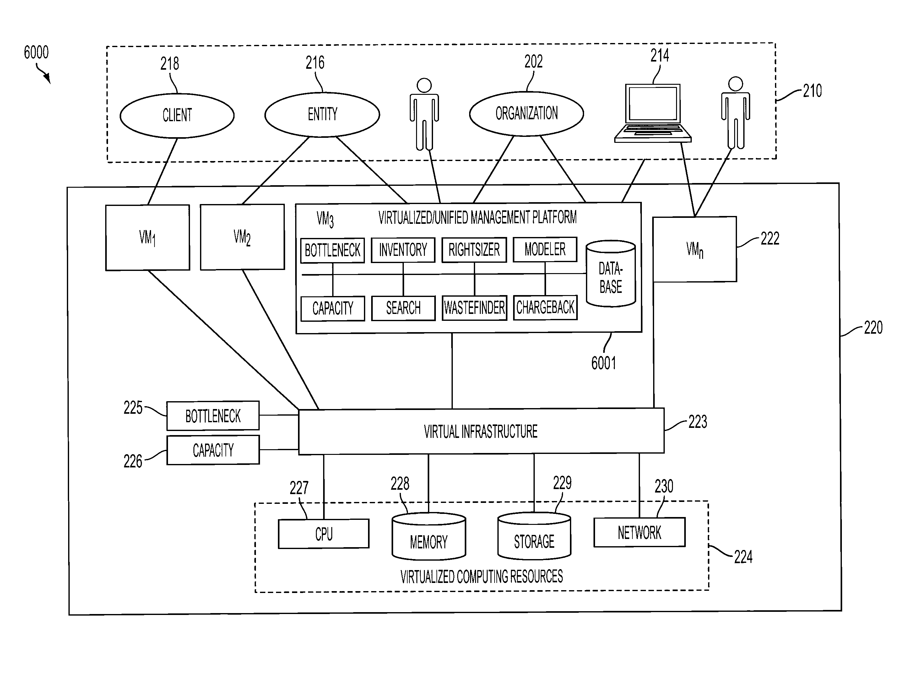
[0020]Yet, another exemplary implementation of the present invention provides a method, apparatus and system for a unified management platform in a virtual computer network, providing a novel approach to system management for virtual resources, providing at least the benefit of optimizing time for system administrators.
[0021]Embodiments of the present invention provide for proactively analyzing and managing shared capacity utilization trends in a virtualized environment utilizing a graphical use interface, providing the benefit of significantly reducing the time and costs of utilizing and maintaining virtualized environments.

Problems solved by technology

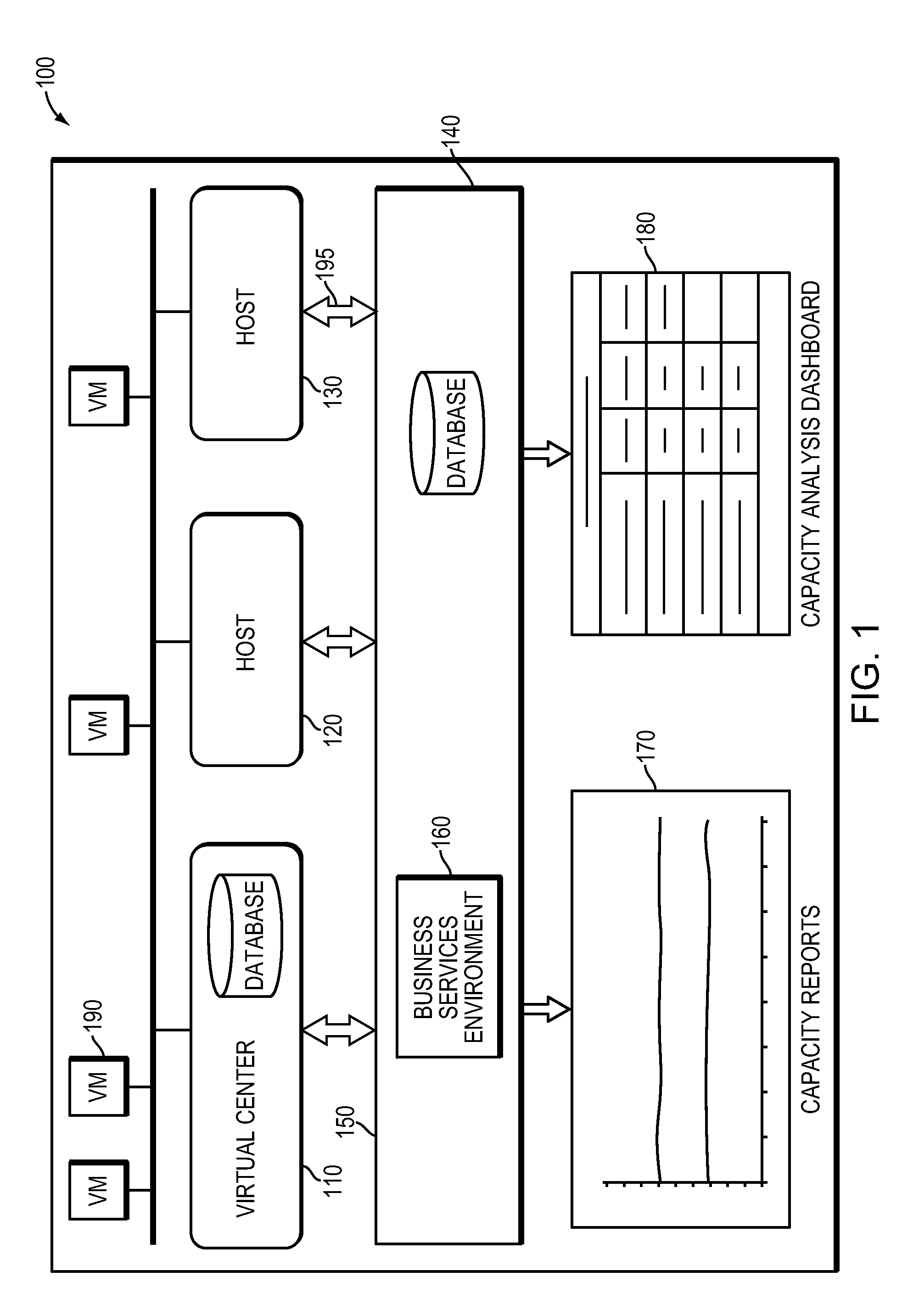
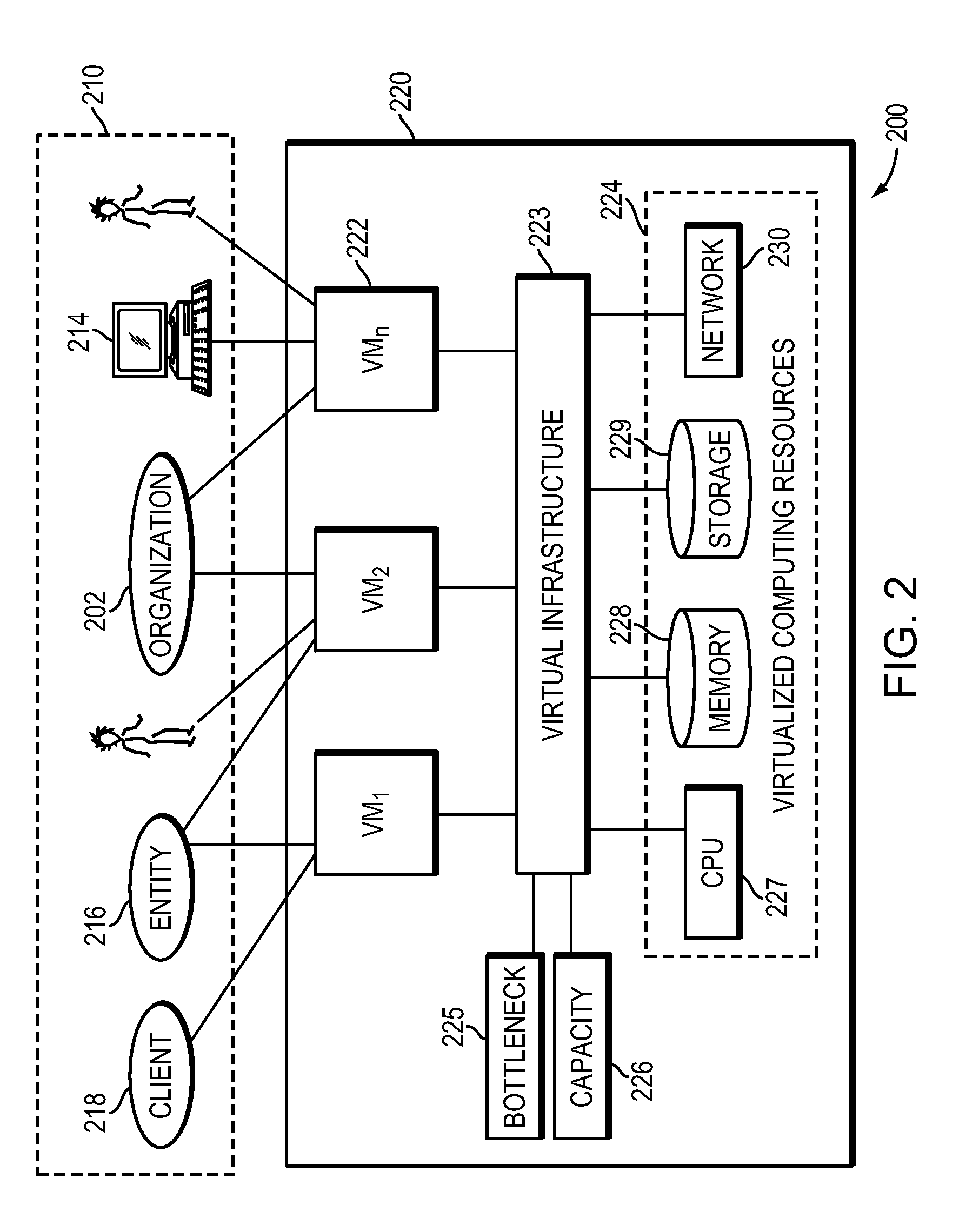
With consolidation of servers it is inevitable that capacity bottlenecks will develop in sharing or resources such as CPU, RAM, and Storage.
That is, if the shared resources are over-utilized, users can experience performance degradation and even downtime.
Conventional approaches for determining capacity bottlenecks is very labor intensive, requiring system administrators to manually examine numerous capacity graphs to determine where bottlenecks exist.
That is, using conventional capacity reporting software is extremely time consuming and requires examination of hundreds of charts.
Furthermore, conventional techniques do not provide any means for proactively managing and allocating shared resources in a virtual environment.
For example, conventional approaches do not anticipate resource allocation or future utilization that may lead to bottlenecks in CPU, memory, storage and disk Input / Output (hereinafter “I / O”), which can lead to performance problems and costly downtime situations.
Likewise, conventional systems do not provide means for dealing with over-allocation of resources which can drive up the cost per virtual machine and diminishing returns on the investment in virtualization.
Furthermore, conventional systems management products are not designed to solve critical virtualization issues at the speed at which an organization (such as an IT organization) demands.
The drawbacks of such conventional systems range from complex implementations and instruction manuals with superfluous information to unnecessary hardware and software resource consumption, as well as delays in deployment and installation.
For example, conventional systems are time consuming, involve repetitive discovery and lack integration among system management applications, amongst other disadvantages and deficiencies.

Method used


Image

  • Unified management platform in a computer network
  • Unified management platform in a computer network
  • Unified management platform in a computer network

Examples


Embodiment Construction

[0040]The matters exemplified in this description are provided to assist in a comprehensive understanding of exemplary embodiments of the present invention described with reference to the accompanying drawing figures. Accordingly, those of ordinary skill in the art will recognize that various changes and modifications of the exemplary embodiments described herein can be made without departing from the scope and spirit of the present invention. Also, descriptions of well-known functions and constructions are omitted for clarity and conciseness. Likewise, certain naming conventions, labels and terms as used in the context of the present disclosure are, as would be understood by skilled artisans, non-limiting and provided only for illustrative purposes to facilitate understanding of certain exemplary implementations of the embodiments of the present invention.

[0041]Exemplary implementations of the present invention provide a method, system and apparatus for proactively managing and all...


PUM


Abstract

A method, system and apparatus for a unified management platform in a computer network such as in a virtualized computer environment, is provided.

Description

CROSS-REFERENCE TO RELATED PATENT APPLICATION[0001]This is a continuation-in-part application under 35 U.S.C. 120 of U.S. Nonprovisional application Ser. No. 12 / 395,524, filed on Feb. 27, 2009 in the U.S. Patent and Trademark Office, the entire disclosure of which is incorporated herein by reference. Additionally, this application claims the benefit under 35 U.S.C. §119(e) of U.S. Provisional Patent Applications Nos.: 61 / 078,285 filed on Jul. 3, 2008; and 61 / 064,474 filed on Mar. 7, 2008 in the U.S. Patent and Trademark Office, the entire disclosures of which are incorporated herein by reference. Additionally, this application is a continuation-in-part of U.S. Non-Provisional patent application Ser. No. 12 / 249,822, filed on Oct. 10, 2008 now abandoned in the U.S. Patent and Trademark Office, the entire disclosure of which is incorporated herein by reference.FIELD OF THE INVENTION[0002]The present application is in the field of computer networks and systems management and is directed...

Claims


Application Information

Patent Timeline
Patent Type & Authority Patents(United States)
IPC IPC(8): G06F9/46G06F11/00G06F11/34H04L12/24H04L12/26
CPCG06F11/008G06F11/3409G06F11/3447G06F11/3466H04L41/145H04L43/0876H04L41/147G06F11/3442G06F2201/815H04L41/024H04L41/22H04L41/149
Inventor BAKMAN, ALEXANDER
Owner QUEST SOFTWARE INC
Learn More