
Ladar backtracking of wake turbulence trailing an airborne target for point-of-origin estimation and target classification

a wake turbulence and target technology, applied in the field of weaponlocating lidar (light detection and ranging) aka ladar system, can solve the problems of less accurate estimation of poo and less effective counterbattery fir

Active Publication Date: 2015-01-27
RAYTHEON CO
View PDF18 Cites 16 Cited by
  • Summary
  • Abstract
  • Description
  • Claims
  • Application Information

AI Technical Summary

Benefits of technology

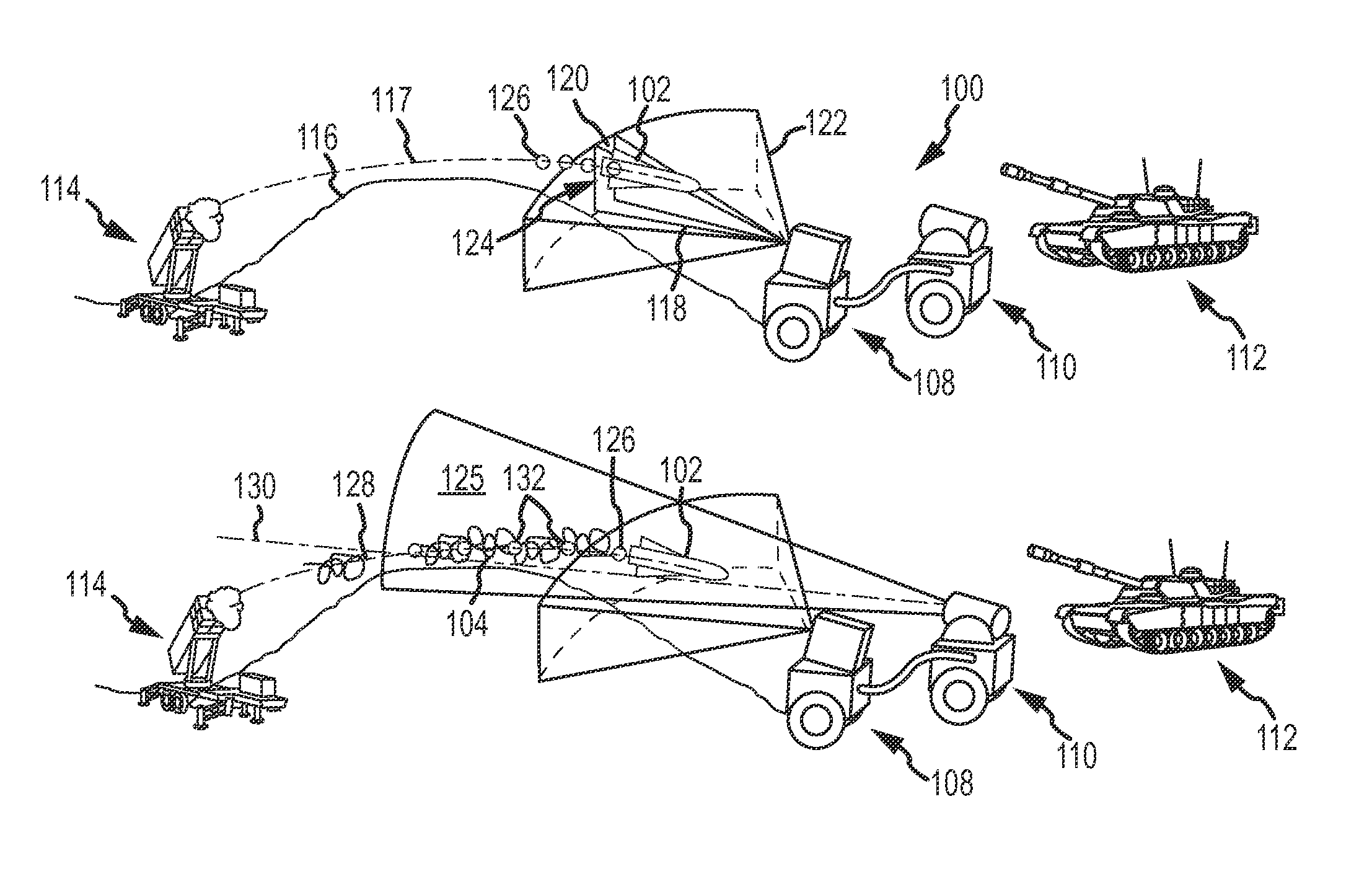
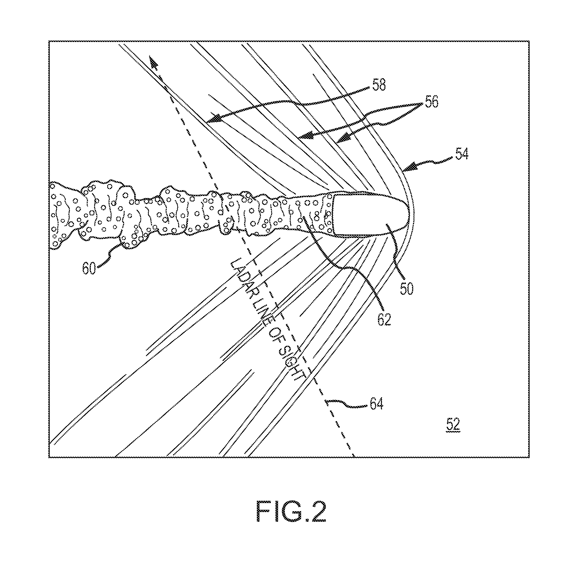
[0010]The present invention provides a weapon-locating ladar system that estimates a backward trajectory of an airborne target by using flow field measurements to follow the wake turbulence trailing the airborne target from the position at which the target is detected backwards towards the source of fire. The system may use the backward trajectory to estimate the point-of-origin of the target. The system may also use the flow field measurements along the backward trajectory to classify the target. Target classification may be used to refine the point-of-origin estimate, to influence counter-fire measures chosen, or to adapt the flow field measurements.
[0017]In an embodiment, the spatial sampling of the backscattered laser energy in the volume of air in and around the wake is adapted in accordance with the flow field measurements, target classification and ladar function.
[0018]In an embodiment, estimates of the wind velocity are extracted from the flow field measurements either inside or outside the wake as the wake turbulence is backtracked. The wind velocities are used to compensate the backward trajectory and POO estimate.

Problems solved by technology

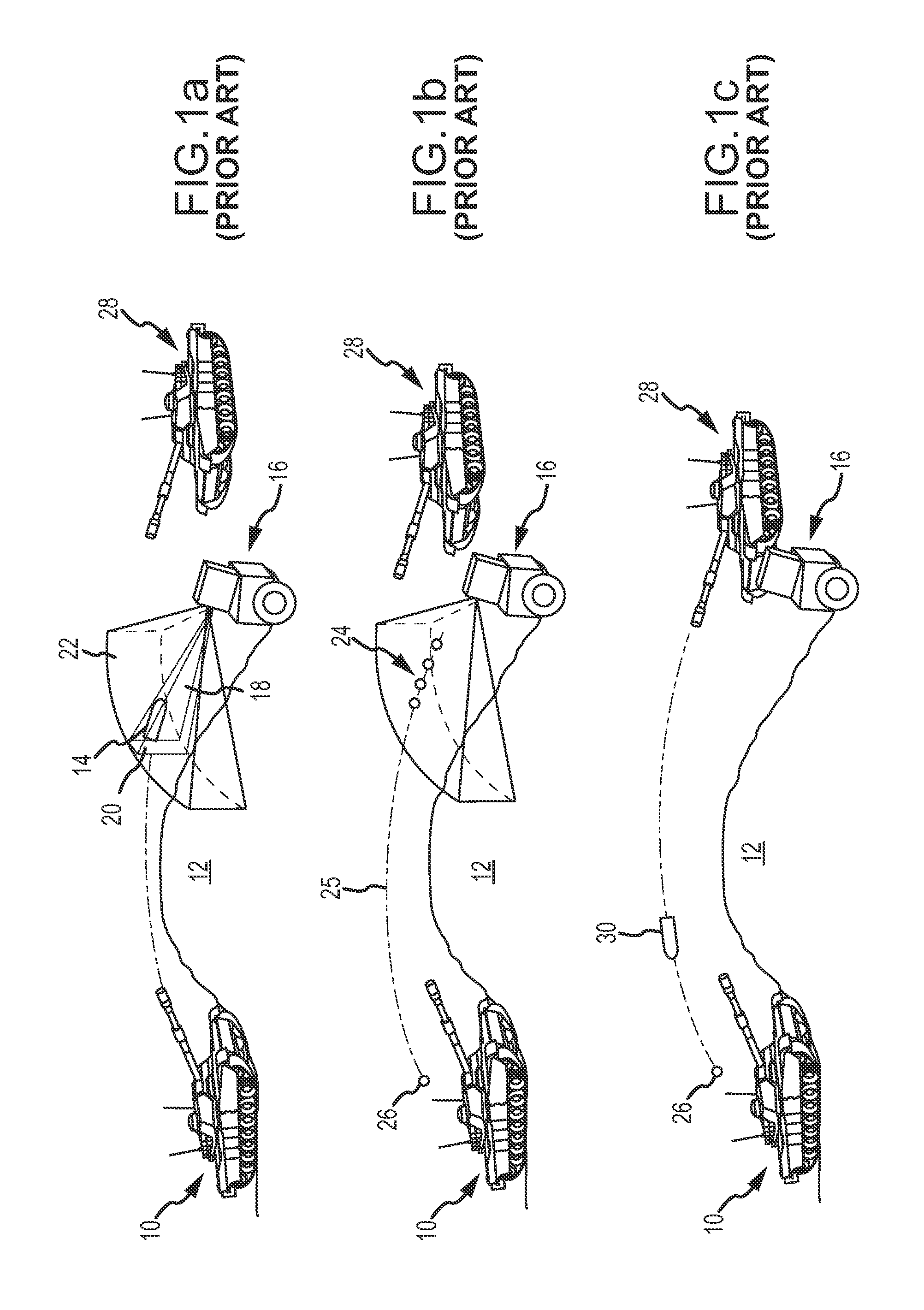
In practice there is a delay, corresponding to many meters of distance travelled, before the system can detect the projectile and establish a stable track.
If these conditions are not met, the estimated POO will be less accurate, and the counterbattery fire will be less effective.

Method used


Image

  • Ladar backtracking of wake turbulence trailing an airborne target for point-of-origin estimation and target classification
  • Ladar backtracking of wake turbulence trailing an airborne target for point-of-origin estimation and target classification
  • Ladar backtracking of wake turbulence trailing an airborne target for point-of-origin estimation and target classification

Examples


Embodiment Construction

[0028]The present invention provides a weapon-locating ladar system that estimates a backward trajectory of an airborne target such as subsonic or supersonic projectiles, rockets, mortars, missiles, etc. by following laser energy backscatter from the wake turbulence trailing the airborne target from a position at which the target is detected backwards until the wake is no longer observable by the ladar system. The weapon-locating system may use the backward trajectory to estimate the POO of the target. The system may also use a signature of the wake along the backward trajectory to classify the target. The wake signature may be combined with a target signature provided by the ladar or a radar system to improve classification. Target classification may be used to refine the POO estimate or to influence counter-fire.

[0029]The use of ladar extends the direct measurement of the target hardbody trajectory back from the point of detection to the point the wake is no longer observable, whi...


PUM

PropertyMeasurementUnit
eye-safe wavelengthsaaaaaaaaaa
velocitiesaaaaaaaaaa
trajectoryaaaaaaaaaa

Abstract

A weapon-locating ladar system estimates a backward trajectory of an airborne target by using flow field measurements to follow the wake turbulence trailing the airborne target from a position at which the target is detected backwards until the wake is no longer observable. The system may use the backward trajectory to estimate the point-of-origin of the target. The system may also use the flow field measurements along the backward trajectory to classify the target. Target classification may be used to refine the point-of-origin estimate, to influence counter-fire or to adapt the flow field measurements.

Description

BACKGROUND OF THE INVENTION[0001]1. Field of the Invention[0002]This invention relates to weapon-locating systems that track the path of incoming airborne targets back to the source of fire and position of the weapon, and more specifically to a new class of weapon-locating lidar (LIght Detection And Ranging) aka ladar system that uses flow field measurements to backtrack the wake turbulence trailing the airborne target from the point the target is detected backwards to estimate a backward trajectory. The backward trajectory can be used to estimate the point-of-origin (POO) of the target. The flow field measurements may also be used to classify the airborne target, which can be used to refine the POO estimate or to influence the counter-fire directed at the POO.[0003]2. Description of the Related Art[0004]Weapon-locating radar (RAdio Detection And Ranging) systems track the path of incoming projectiles including shells, rockets, mortars, missiles etc., and calculate the point from wh...

Claims


Application Information

Patent Timeline
Patent Type & Authority Patents(United States)
IPC IPC(8): F42C13/02F42C13/04G01S13/86G01S13/38G01N21/84G01S17/86
CPCG01S7/4802G01S17/58G01S17/66G01S17/88G01S17/95G01S7/003G01S17/86Y02A90/10F41H13/00G01S13/06G01S13/865
Inventor SMITH, DUANE DONALDBYREN, ROBERT WILLIAM
Owner RAYTHEON CO
Learn More