Battery state monitoring circuit and battery device

a battery state monitoring and battery device technology, applied in safety/protection circuits, cell components, instruments, etc., can solve the problems of unbalanced voltage between secondary batteries, and stop discharge, so as to prevent the shortened life of battery devices

Active Publication Date: 2015-01-27
ABLIC INC
View PDF6 Cites 2 Cited by
  • Summary
  • Abstract
  • Description
  • Claims
  • Application Information

AI Technical Summary

Benefits of technology

[0011]According to the battery device of the present invention, when one secondary battery is detected to be overcharged or overdischarged, power is not consumed in only the one secondary battery and hence voltages between the secondary batteries can be prevented from being unbalanced. Therefore, the life of the battery device can be prevented from being shortened.

Problems solved by technology

The conventional technology, however, has a problem that, if only the secondary battery 301 becomes the overcharged state or the overdischarged state, power of only the secondary battery 301 is consumed by the voltage detection circuit 305 to result in unbalanced voltages between the secondary batteries.
If the secondary batteries are charged under the unbalanced voltage state, the charge is stopped when the secondary battery with the highest voltage becomes the overcharged state even if the other batteries have not been sufficiently charged.
On the other hand, if the secondary batteries are discharged under the unbalanced voltage state, the discharge is stopped when the secondary battery with the lowest voltage becomes the overdischarged state even if the other batteries still have high voltages.
Therefore, there is a problem that the life of the battery device is shortened.

Method used


Image

  • Battery state monitoring circuit and battery device
  • Battery state monitoring circuit and battery device
  • Battery state monitoring circuit and battery device

Examples


first embodiment

[First Embodiment]

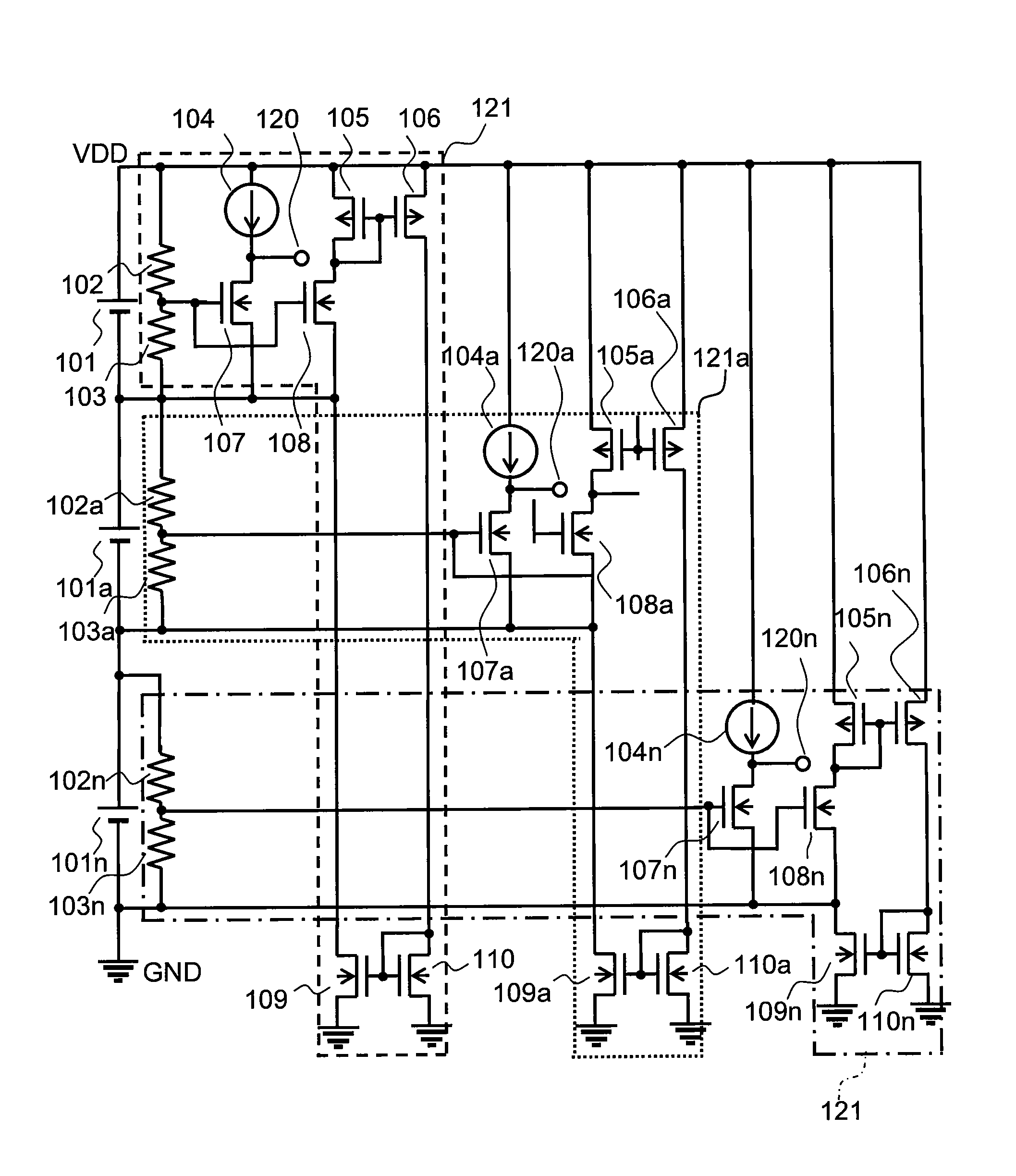
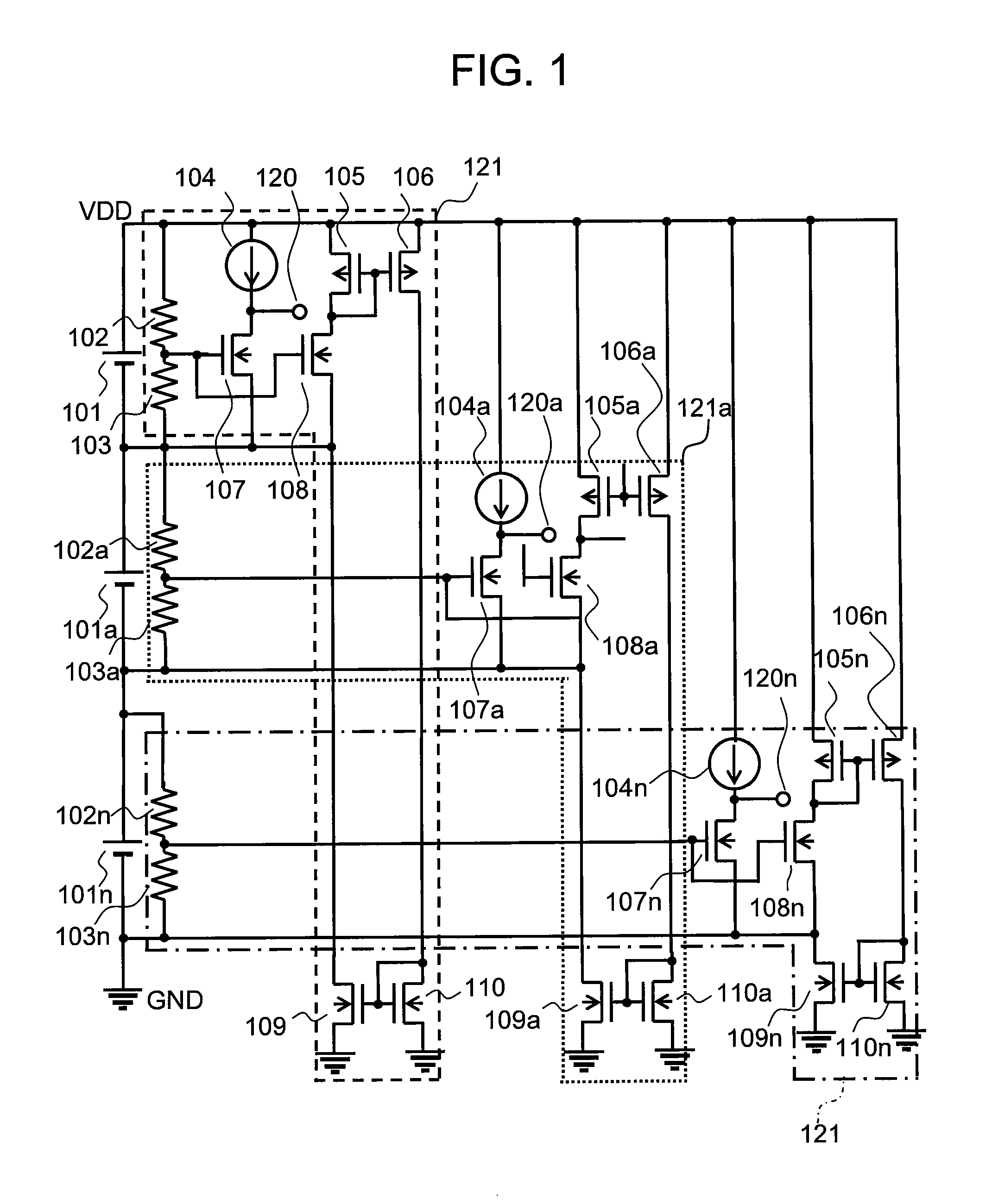
[0020]FIG. 1 is a circuit diagram of a battery state monitoring circuit according to a first embodiment of the present invention.

[0021]The battery state monitoring circuit according to the first embodiment includes n voltage detection sections 121 to 121n which are individually provided corresponding to the n series-connected secondary batteries 101 to 101n.

[0022]The voltage detection section 121 includes a voltage detection circuit and a current bypass circuit. The voltage detection circuit includes a constant current circuit 104 and an NMOS transistor 107. The current bypass circuit includes NMOS transistors 108, 109, and 110 and PMOS transistors 105 and 106.

[0023]The other voltage detection sections 121a to 121n have the same components as those of the voltage detection section 121.

[0024]Connection in the voltage detection section 121 is described. A resistor 102 has one end connected to a positive terminal of the secondary battery 101 (hereinafter, referred to...

second embodiment

[Second Embodiment]

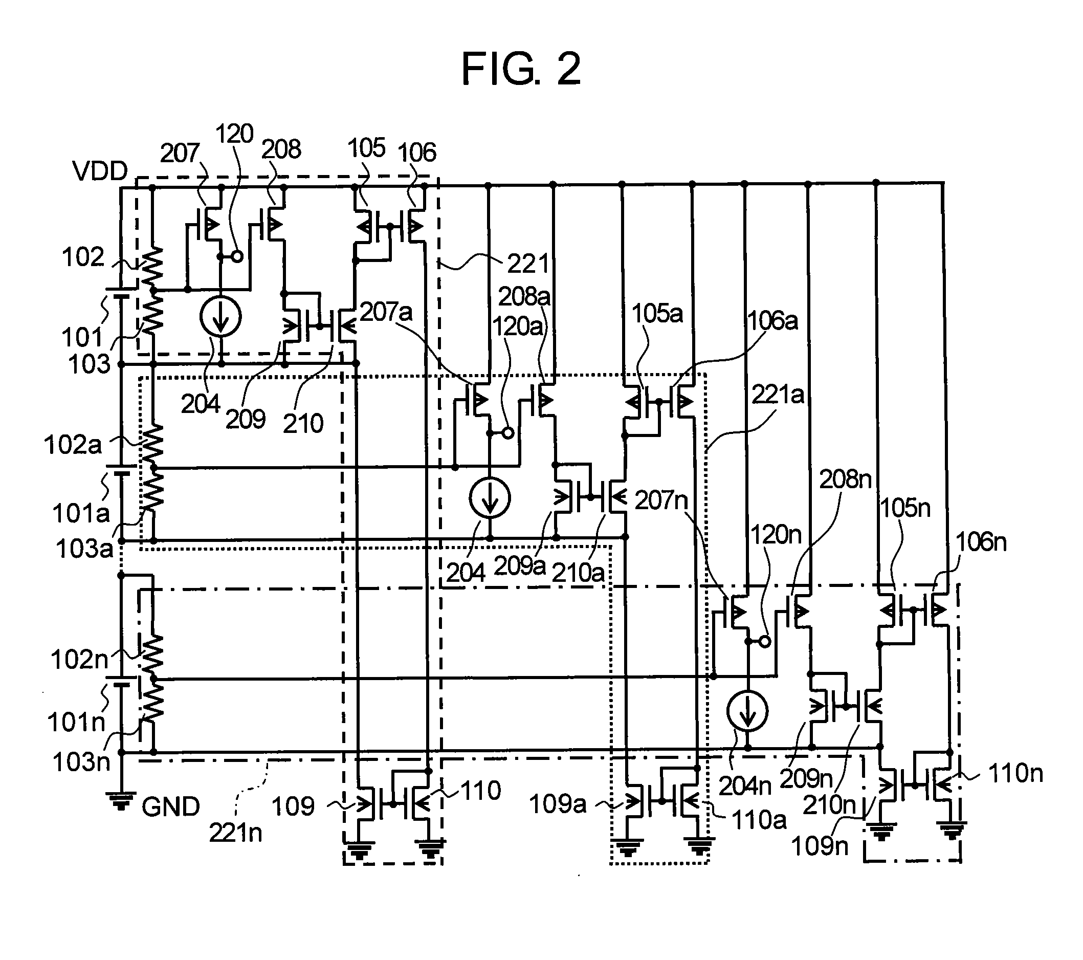
[0030]FIG. 2 is a circuit diagram of a battery state monitoring circuit according to a second embodiment of the present invention.

[0031]FIG. 2 is different from FIG. 1 in that the NMOS transistors 107, 107a to 107n, 108, and 108a to 108n are changed to PMOS transistors 207, 207a to 207n, 208, and 208a to 208n, and NMOS transistors 209, 209a to 209n, 210, and 210a to 210n are added.

[0032]Connection in a voltage detection section 221 is described. The PMOS transistor 207 has a gate connected to the connection point between the resistors 102 and 103 and to a gate of the PMOS transistor 208. The PMOS transistor 207 has a drain connected to the output terminal 120 and a source connected to the VDD terminal. The PMOS transistor 208 has a drain connected to a drain and a gate of the NMOS transistor 209, and a source connected to the VDD terminal. A constant current circuit 204 has one end connected to the output terminal 120 and another end connected to the negative term...


PUM

PropertyMeasurementUnit
voltageaaaaaaaaaa
operation currentaaaaaaaaaa
currentaaaaaaaaaa

Abstract

Provided are a battery state monitoring circuit and a battery device, in which, even when one secondary battery becomes an overcharged state or an overdischarged state and then a voltage detection circuit operates, power is not consumed in only the one secondary battery. The battery state monitoring circuit includes: a plurality of voltage detection circuits which are provided for a plurality of secondary batteries, respectively, for detecting voltages of the plurality of secondary batteries; and a current bypass circuit provided in each of the plurality of voltage detection circuits, for allowing an operation current of the each of the plurality of voltage detection circuits to flow into a ground terminal. Therefore, when only one secondary battery becomes an overcharged state or an overdischarged state, the battery device operates so that the power of all the secondary batteries is consumed to prevent voltages between the secondary batteries from being unbalanced.

Description

RELATED APPLICATIONS[0001]This application claims priority under 35 U.S.C. §119 to Japanese Patent Application No. 2010-129030 filed on Jun. 4, 2010, the entire content of which is hereby incorporated by reference.BACKGROUND OF THE INVENTION[0002]1. Field of the Invention[0003]The present invention relates to a battery state monitoring circuit for controlling charge / discharge of a plurality of secondary batteries, and a battery device including the battery state monitoring circuit.[0004]2. Description of the Related Art[0005]FIG. 4 illustrates a circuit diagram of a conventional battery device. In the conventional battery device, two batteries 301 and 302 as secondary batteries are interposed in series between power supply terminals +VB and −VB of a battery state monitoring circuit. A connection point between the two batteries is connected to a VI terminal of the battery state monitoring circuit. A voltage of the battery 301 is divided by a voltage dividing circuit 304. The divided ...

Claims


Application Information

Patent Timeline
Patent Type & Authority Patents(United States)
IPC IPC(8): H02J7/00G01N27/416H02J7/02G01R31/36H01M10/48H01M50/569
CPCH02J7/0016H02J7/0026H01M10/482G01R31/3658G01R31/396Y02E60/10H02J7/00302H02J7/00306H01M50/569G01R19/16542G01R31/382G01R31/385H02J7/0048H02J7/005
Inventor SAITO, HIROSHISANO, KAZUAKI
Owner ABLIC INC
Why Eureka
Try Eureka