Light-emitting device, electronic device, and driving method thereof
a technology of light-emitting devices and electronic devices, which is applied in the direction of color television details, instruments, television systems, etc., can solve the problems of image burn-in, extremely high voltage, and reduce display uniformity, so as to reduce display uniformity
- Summary
- Abstract
- Description
- Claims
- Application Information
AI Technical Summary
Benefits of technology
Problems solved by technology
Method used
Image
Examples
embodiment 1
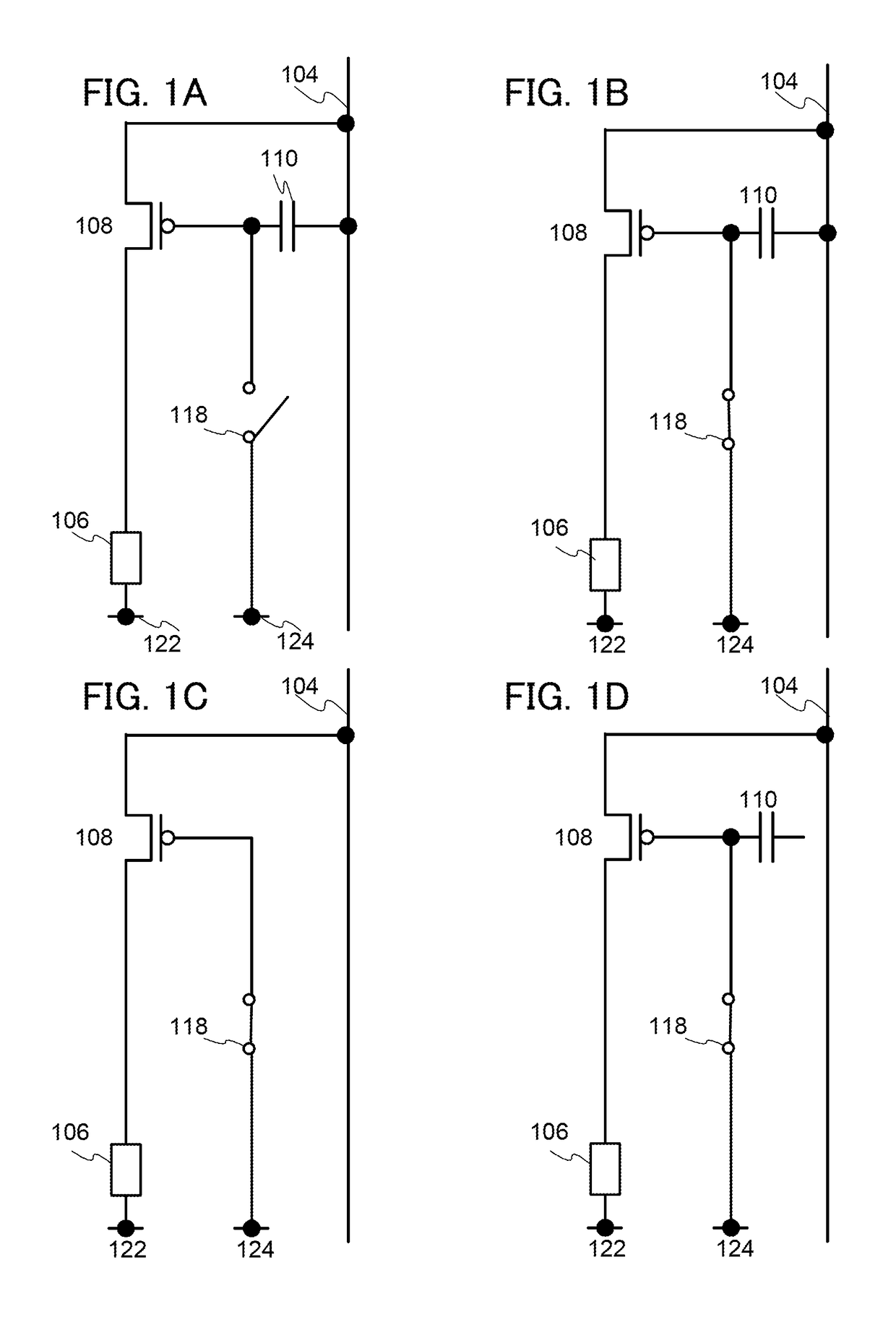
[0109]In this embodiment, a method for driving a light-emitting device which is one embodiment of the present invention is described.
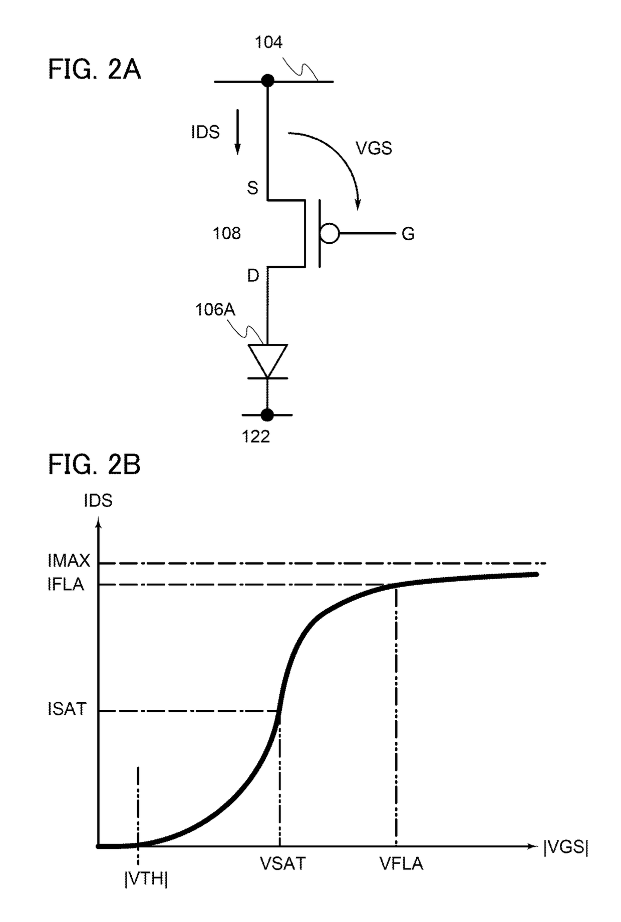
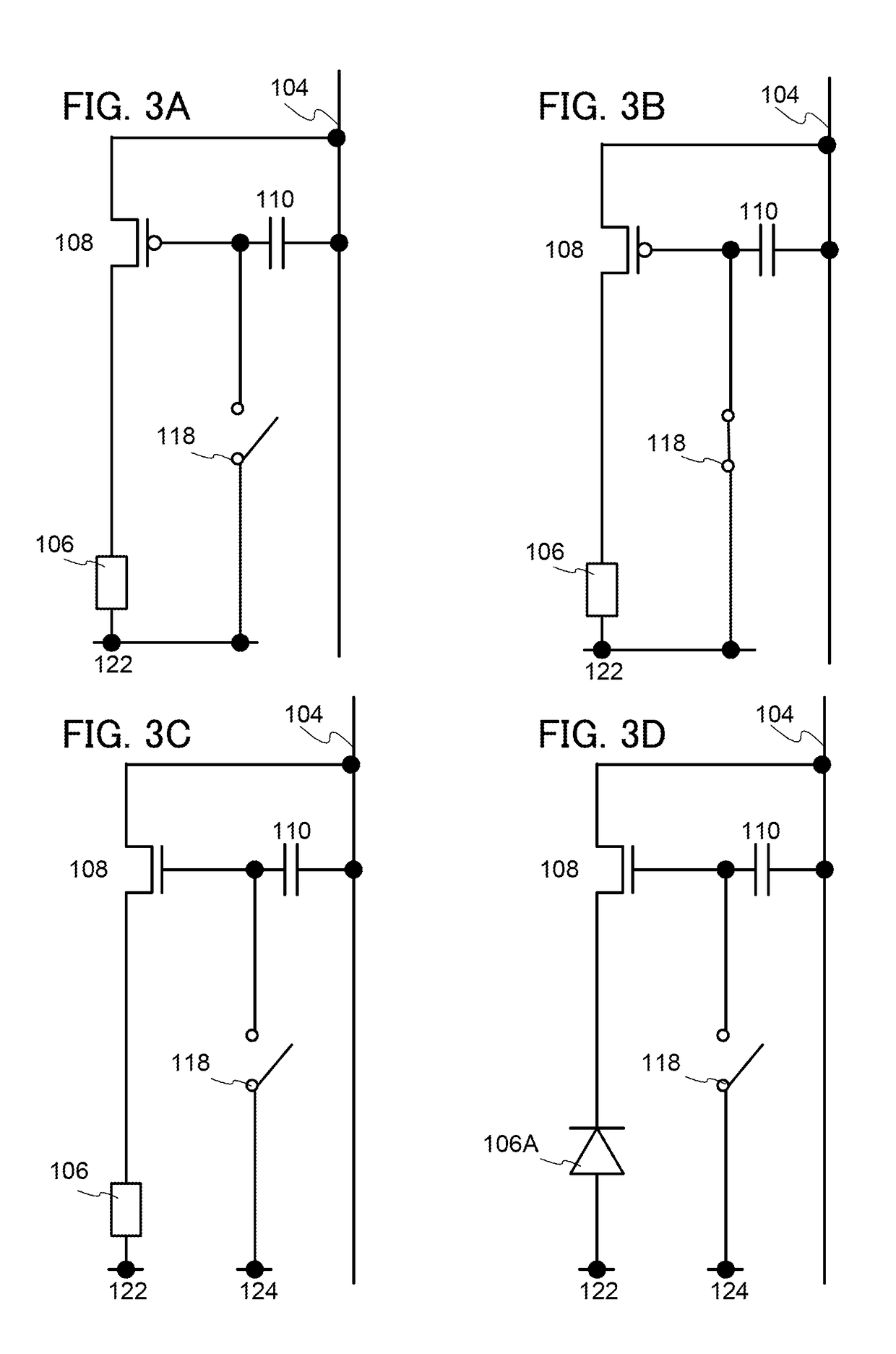
[0110]The light-emitting device has a display function and a lighting function for illuminating a subject using a camera, for example. The display function is a function of displaying text and images, which is a common function of display devices. The lighting function is a function of illuminating a subject or the like with high-luminance illumination light. In this light-emitting device, these functions or operations can be switched. Note that a driving method and a state for performing the display function are different from those for performing the lighting function, for example.
[0111]Note that the purpose and function of the lighting function are not limited to the improvement of the illuminance of a subject. For example, the lighting function may be used only for brightening up a dark part, for anticrime measures, for traffic accident countermeas...
embodiment 2
[0129]In this embodiment, a specific example of a light-emitting device of one embodiment of the present invention and a driving method thereof will be described.
[0130]FIG. 5 shows a specific example of a circuit including the circuit shown in FIG. 1A. FIG. 5 corresponds to one pixel. The wiring 102 is connected to the gate of the transistor 108 through a switch 312.
[0131]The wiring 102 has a function of supplying or transmitting a video signal. A precharge signal or an initialization signal may be supplied to the wiring 102. The wiring 102 may have a function of supplying or transmitting a signal to the switch 312. The wiring 102 thus serves as at least one of a video signal wiring, a source signal wiring, an initialization signal wiring, and the like.
[0132]The wiring 104 has a function of supplying or transmitting voltage or current to the transistor 108. The wiring 104 may have a function of supplying or transmitting voltage or current to the load 106. The wiring 104 may have a f...
embodiment 3
[0162]In this embodiment, another specific example of a light-emitting device of one embodiment of the present invention and a driving method thereof will be described.
[0163]FIG. 15 shows a specific example of a circuit including the circuit shown in FIG. 1A. FIG. 15 corresponds to one pixel. The wiring 102 is connected to the source of the transistor 108 through a switch 112. The switch 114 is connected between the source of the transistor 108 and the wiring 104. The switch 116 is connected between the gate and the drain of the transistor 108. The switch 120 is connected between the drain of the transistor 108 and the load 106.
[0164]The wiring 102 has a function of supplying or transmitting a video signal. A precharge signal or an initialization signal may be supplied to the wiring 102. The wiring 102 may have a function of supplying or transmitting a signal to the switch 112. The wiring 102 thus serves as at least one of a video signal wiring, a source signal wiring, an initializa...
PUM
 Abstract
Description
Claims
Application Information
 - R&D
- Intellectual Property
- Life Sciences
- Materials
- Tech Scout
- Unparalleled Data Quality
- Higher Quality Content
- 60% Fewer Hallucinations
Browse by: Latest US Patents, China's latest patents, Technical Efficacy Thesaurus, Application Domain, Technology Topic, Popular Technical Reports.
© 2025 PatSnap. All rights reserved.Legal|Privacy policy|Modern Slavery Act Transparency Statement|Sitemap|About US| Contact US: help@patsnap.com


