Contact switching device

a switching device and contact technology, applied in the direction of magnets, relays, magnetic bodies, etc., can solve the problems of increasing sound pressure, achieve the effect of convenient silence design, desired buffer performance, and stable supporting for

Active Publication Date: 2015-01-27
ORMON CORP
View PDF114 Cites 21 Cited by
  • Summary
  • Abstract
  • Description
  • Claims
  • Application Information

AI Technical Summary

Benefits of technology

[0008]According to the present invention, a structure is such that at the time of return, the annular flange portion provided at the intermediate portion of the movable shaft abuts on the internal fixed component. This allows vibration to be absorbed and alleviated by the internal fixed component even if hitting sound is generated at the time of return, and thus, the return sound is hardly transmitted outside, so that the contact switching device having small return sound can be obtained.
[0009]As an embodiment of the present invention, a buffer material may be disposed between a bottom-surface back side of the internal fixed component and a second internal fixed component fixing the internal fixed component.
[0010]According to the present embodiment, the vibration is absorbed and alleviated by the buffer material through the internal fixed component with the movable shaft assembled, and thus, the return sound is hardly transmitted outside, so that the contact switching device having smaller return sound can be obtained. As the buffer material, the block-like buffer material and the sheet-like buffer material are cited.
[0011]As another embodiment of the present invention, the buffer material may has a block shape which in a plan view has an appearance which looks substantially like the number 8.
[0012]According to the present embodiment, desired buffer performance can be exerted while assuring a stable supporting force. Particularly, not only selection of a material can assure the desired buffer performance, but also change of the shape can assure the desired buffer performance, which makes silence design easy.
[0013]As another embodiment of the present invention, the buffer material may have a sheet shape.

Problems solved by technology

However, the foregoing contact switching device has a problem that since a movable iron core 8 hits a bottom surface of a bottomed cylindrical portion 10 at the time of return, hitting sound transmits to outside through an externally attached component from a housing, which increases sound pressure at the time of return, thereby causing stridency.

Method used


Image

  • Contact switching device
  • Contact switching device
  • Contact switching device

Examples


example 1

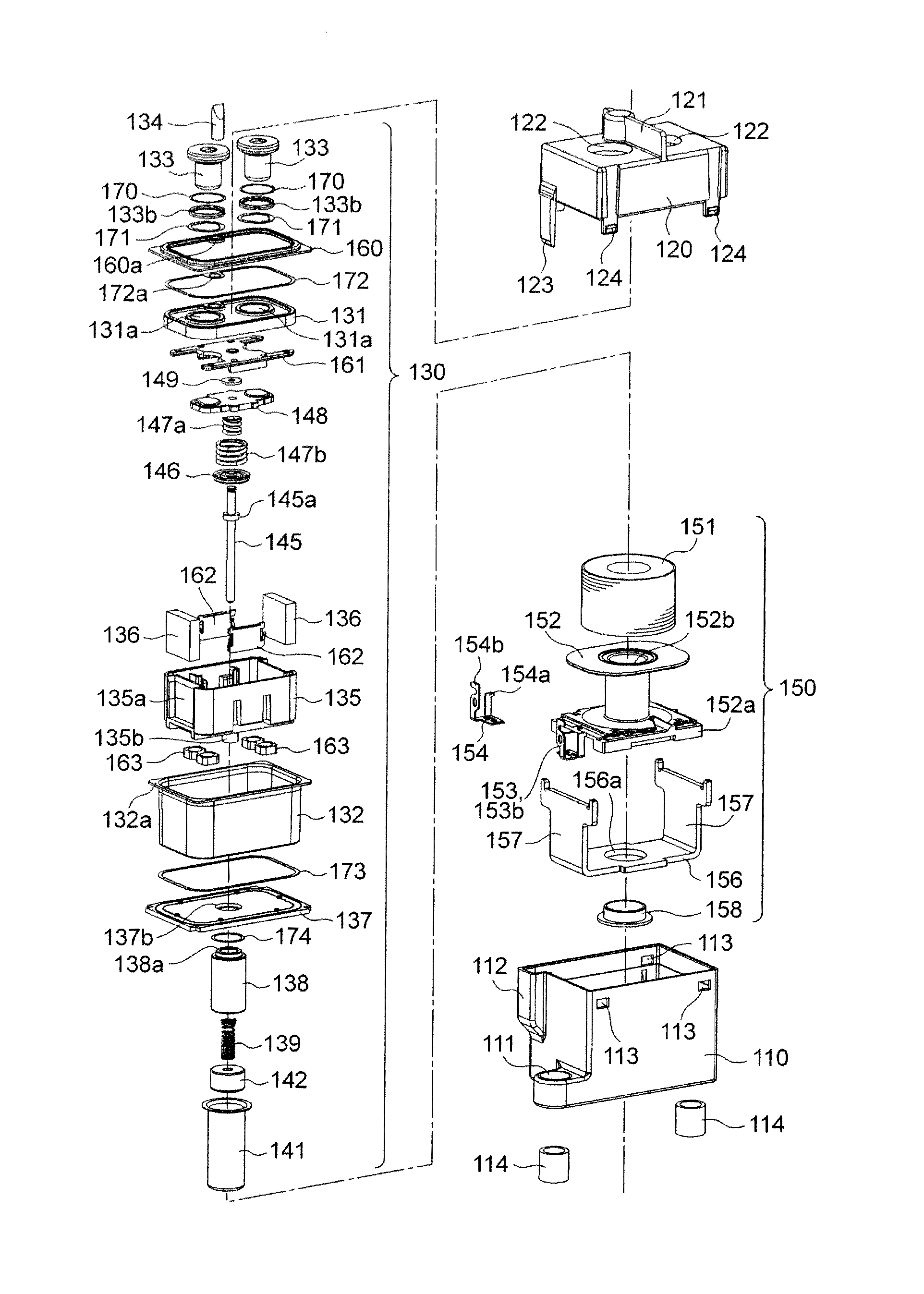
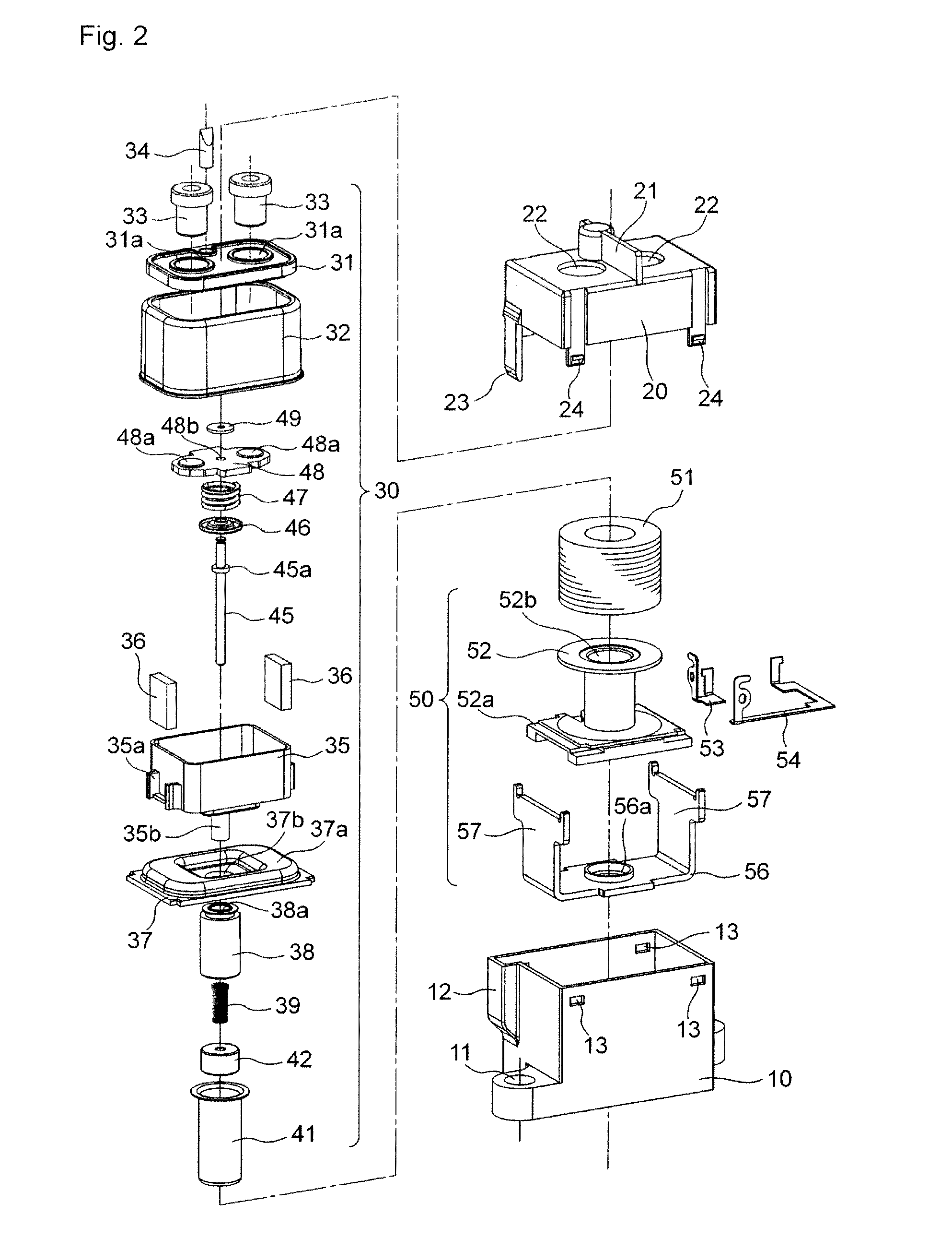
[0149]In the contact switching device of the second embodiment, using a case where only the 8-shaped buffer materials 163 made of CR rubber were incorporated as a sample of Example 1, and a case where the buffer materials 163 were not incorporated as a sample of Comparative Example 1, return sound of both was measured.

[0150]As a result of measurement, in the example and the comparative examples, a decrease by 5.6 dB could be confirmed in the return sound.

example 2

[0151]In the contact switching device of the second embodiment, using a case where only the sheet-like buffer materials were incorporated as a sample of Example 2, and a case where the sheet-like buffer materials were not incorporated as a sample of Comparative Example 2, the return sound of both was measured.

[0152]As a result of measurement, as compared with the return sound of Comparative Example 2, a decrease in the return sound by 11.6 dB could be confirmed in the sheet-like buffer materials made of copper having a thickness of 0.3 mm according to Example 2, a decrease in the return sound by 10.6 dB could be confirmed in the sheet-like buffer materials made of SUS having a thickness of 0.3 mm, and a decrease in the return sound by 8.6 dB could be confirmed in the sheet-like buffer materials made of aluminum having a thickness of 0.3 mm, so that silencing was found to be enabled.

example 3

[0153]In the contact switching device of the second embodiment, using a case where the substantially 8-shaped buffer materials made of CR rubber and the sheet-like buffer materials were combined as a sample of Example 3, and a case where none of the buffer materials was assembled as a sample of Comparative Example 3, the return sound of both was measured.

[0154]As a result of measurement, as compared with the return sound of Comparative Example, a decrease in the return sound by 15.9 dB could be confirmed in the combination of the 8-shaped buffer materials and the sheet-like buffer materials made of copper having a thickness of 0.3 mm according to Example 3, a decrease in the return sound by 18 dB could be confirmed in the 8-shaped buffer materials and the sheet-like buffer materials made of SUS having a thickness of 0.3 mm, and a decrease in the return sound by 20.1 dB could be confirmed in the 8-shaped buffer materials and the sheet-like buffer materials made of aluminum having a t...


PUM


Abstract

An object of the invention is to provide a contact switching device that produces minimal hitting sound at the time of return. In the contact switching device, a movable iron core (42) provided at one end portion of a movable shaft (45) is attracted to a fixed iron core (38), based on excitation and degauss of an electromagnet portion (50), by which the movable shaft (45) reciprocates in a shaft center direction, and a movable contact (48a) of a movable contact piece (48) arranged at another end portion of the movable shaft (45) contacts and departs from a fixed contact (33a). Particularly, at the time of return, an annular flange portion (45a) provided at an intermediate portion of the movable shaft (45) abuts on an annular receiving portion (35c) of the magnet holder (35) to thereby restrict a position of the movable iron core (42).

Description

[0001]This is a non-provisional application claiming the benefit of International Application Number PCT / JP2011 / 055928 filed Mar. 14, 2011.TECHNICAL FIELD[0002]The present invention relates to a contact switching device, and particularly to a contact switching device suitable for a relay for power load, an electromagnetic switch or the like.BACKGROUND ART[0003]Conventionally, as a contact switching device, as shown in Patent Document 1, there has been a contact switching device in which a movable contact 3a of a movable contactor 3 contacts and departs from a fixed contact 2a of a fixed terminal 2 inside a sealed space formed by brazing an opening edge portion of a box-like sealed vessel 1 to an upper surface of a second bonding member 12. Particularly, in the foregoing contact switching device, a voltage is applied / stopped to a coil 13 to thereby perform excitation / degauss, by which a movable shaft 4 is reciprocated in a shaft center direction.[0004]Patent Document 1: Japanese Pate...

Claims


Application Information

Patent Timeline
Patent Type & Authority Patents(United States)
IPC IPC(8): H01H50/34H01H1/36H01H1/66H01H9/44H01H50/00H01H50/02H01H50/04H01H50/30H01H50/40H01H50/44H01H50/54H01H50/60H01H51/00H01H51/06
CPCH01H1/36H01H1/66H01H50/40H01H50/60H01H51/06H01H50/00H01H50/30H01H50/54H01H50/045H01H51/00H01H50/02H01H9/443H01H50/443H01H2050/025H01H50/36H01H50/546
Inventor YANO, KEISUKEHASHIMOTO, RYUICHIHAYASHIDA, YASUOMORI, SHINGO
Owner ORMON CORP
Why Eureka
Try Eureka