Optical deflector

a technology of optical deflector and optical lens, applied in the field of optical deflector, to achieve the effect of large deflection angl

Active Publication Date: 2015-01-27
STANLEY ELECTRIC CO LTD
View PDF4 Cites 4 Cited by
  • Summary
  • Abstract
  • Description
  • Claims
  • Application Information

AI Technical Summary

Benefits of technology

[0011]An object of the invention is to provide an optical deflector which can effectively suppress occurrence of a ringing phenomenon when a piezoelectric actuator is driven with a voltage signal of a sawtooth waveform.
[0013]According to the present invention, the control unit detects the mechanical natural frequency relevant to swinging of the mirror part about the predetermined axis through the use of the natural frequency detecting unit. The control unit applies the voltage signal, which is obtained by removing the natural frequency detected by the natural frequency detecting unit and the harmonic component of the natural frequency within the predetermined frequency range from the voltage signal generated by the voltage signal generating unit, as the drive voltage to the piezoelectric actuator. Accordingly, even when the natural frequency varies depending on the manufacturing error or the like of the optical deflector, it is possible to detect an appropriate natural frequency.
[0016]Therefore, even when the natural frequency varies depending on manufacturing error, disturbance, usage, or the like, it is possible to appropriately suppress the ringing phenomenon. At this time, since the frequency components are removed only within the predetermined frequency range, it is possible to suppress degradation in scanning speed uniformity of the optical deflector. Accordingly, it is possible to secure a scanning section which can be effectively used without increasing a deflection angle of the optical deflector.
[0018]Accordingly, the natural frequency is detected on the basis of the voltage signal output from the detecting piezoelectric element. In this wing, since the natural frequency is detected from the actual behavior, of the optical deflector, it is possible to accurately detect the natural frequency and it is also possible to more effectively suppress the ringing phenomenon.
[0020]Accordingly, even when the individual piezoelectric cantilevers have small bending deformation, the bending deformation can be accumulated and it is thus possible to obtain a large deflection angle. Therefore, it is possible to actuate the mirror part of the optical deflector at frequencies other than the resonance frequency instead of the resonance frequency.

Problems solved by technology

However, in the optical deflector disclosed in Patent Document 1, it is not detected whether a ringing phenomenon occurs when the mirror part is actually actuated.

Method used


Image

  • Optical deflector
  • Optical deflector
  • Optical deflector

Examples


Embodiment Construction

[0028]An optical deflector according to an embodiment of the invention will be described below.

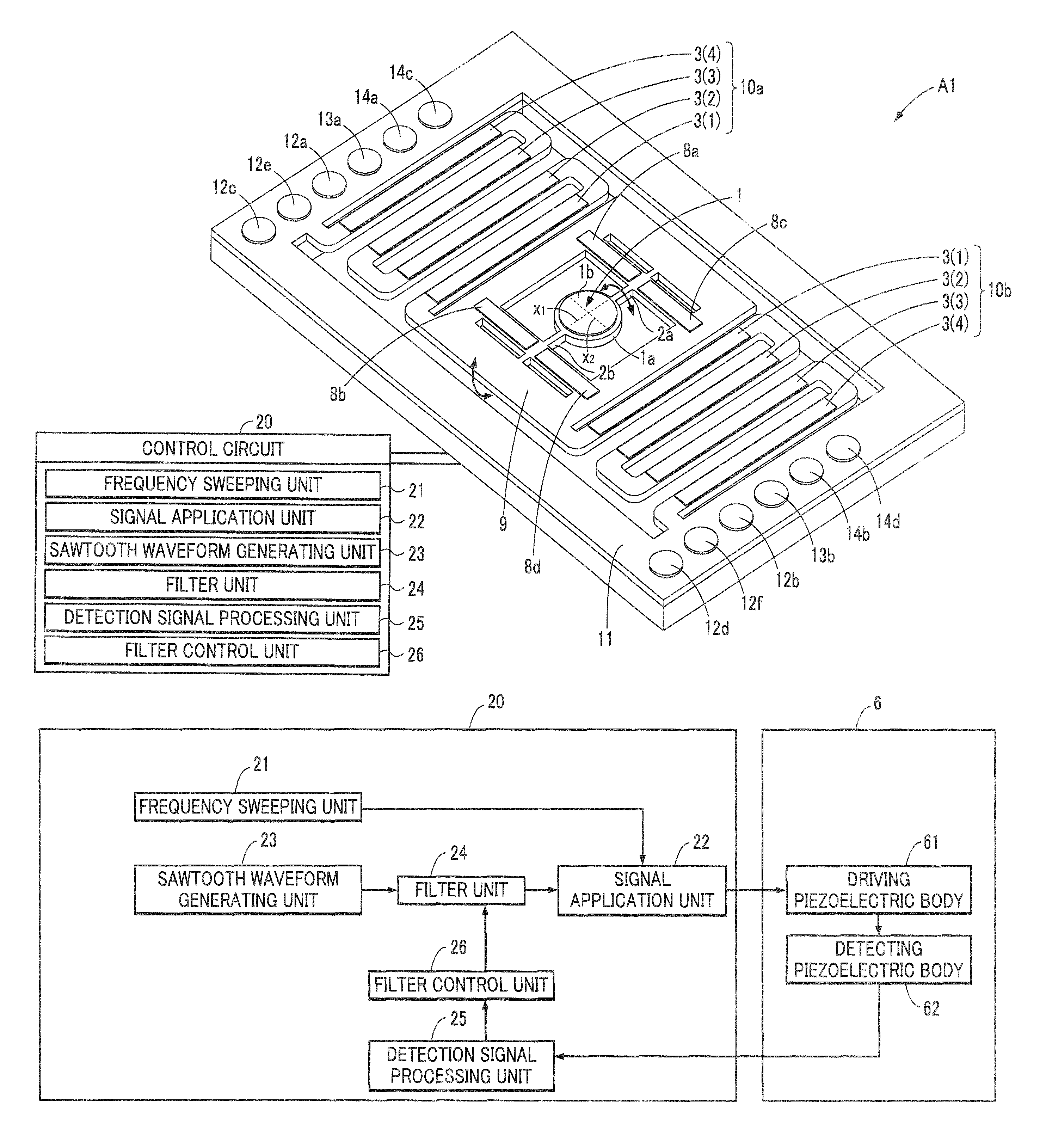
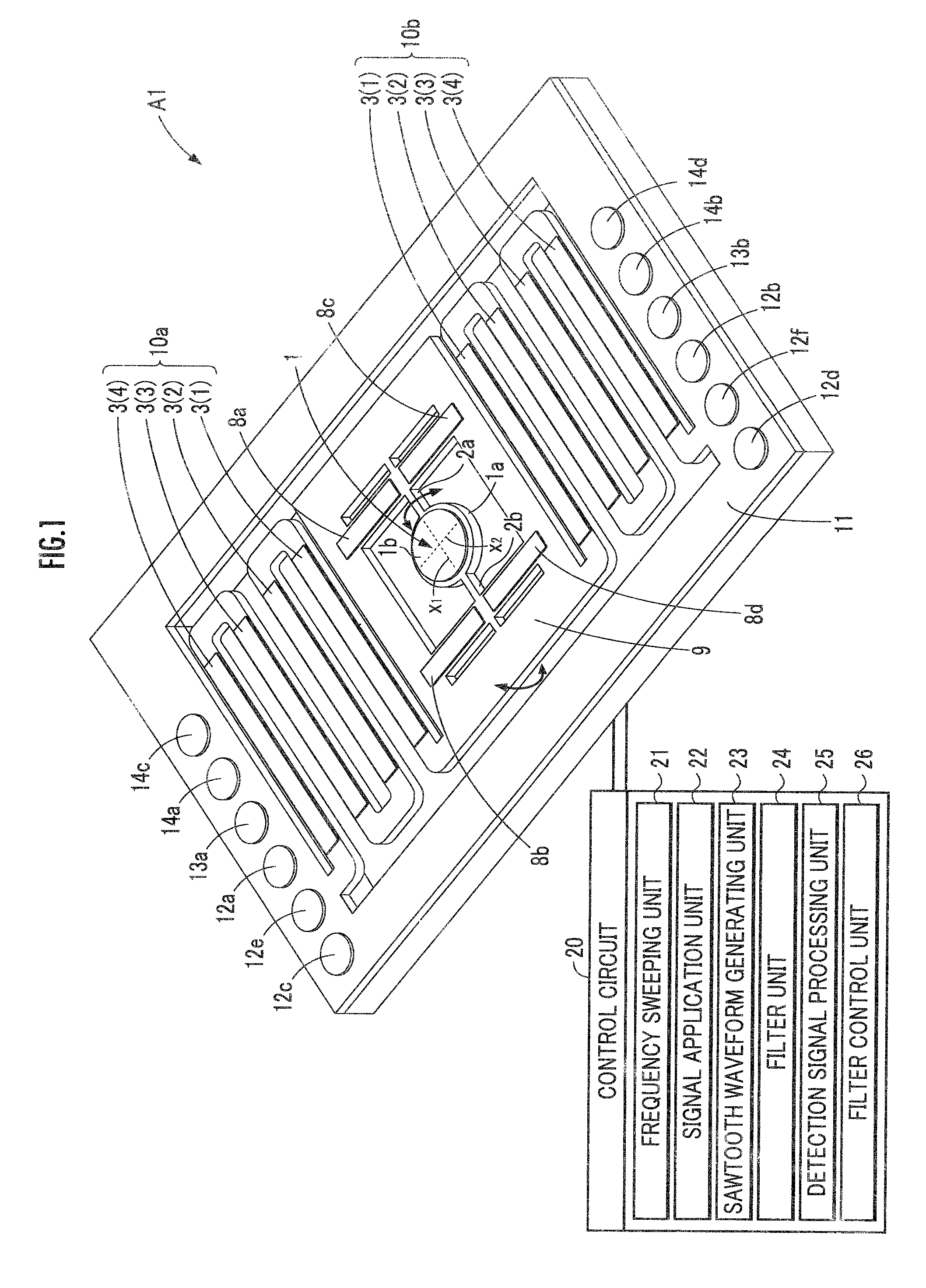
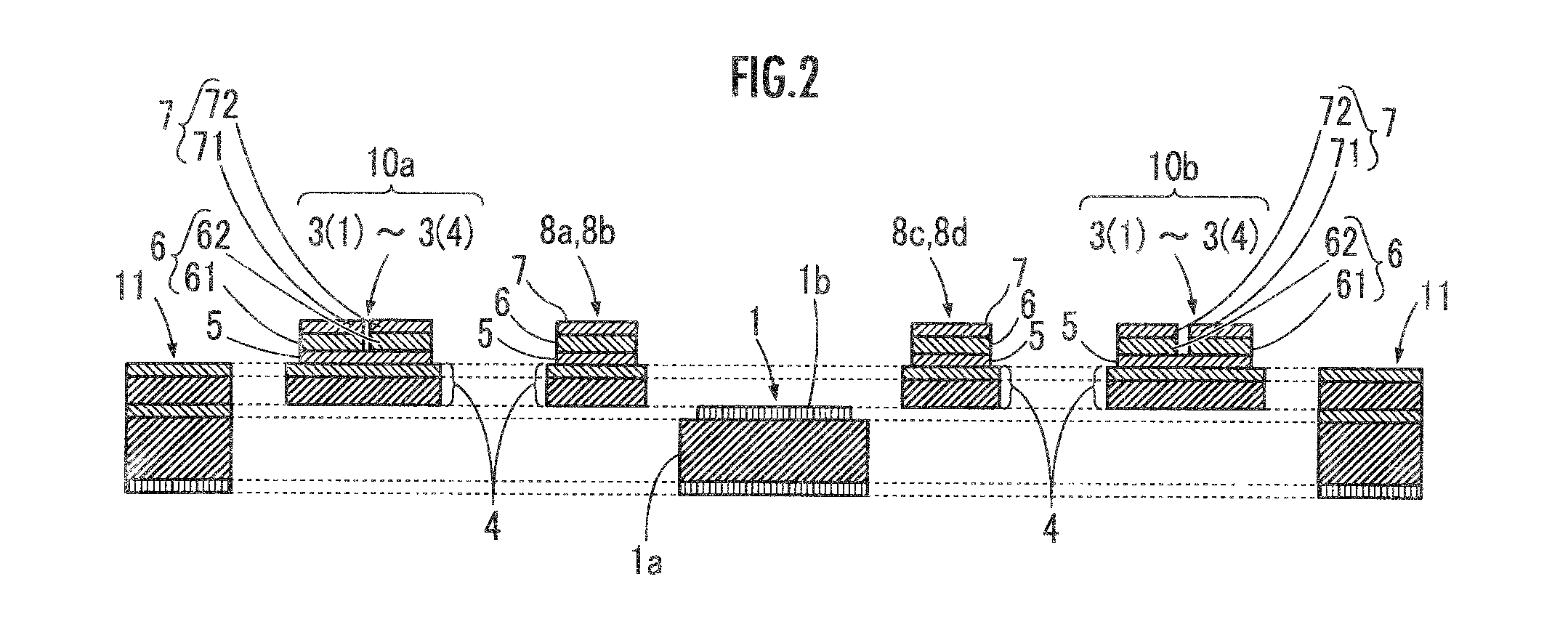
[0029]As illustrated in FIG. 1, an optical deflector A1 according to the present embodiment includes a reflection part 1 that reflects incident light, a movable part 9 on which the reflection part 1 is mounted, piezoelectric actuators 8a, 8b, 8c, and 8d that swing the reflection part 1 about a first axis X1 relative to the movable part 9, and piezoelectric actuators 10a and 10b that swing the reflection part 1 and the movable part 9 about a second axis X2 relative to a support base 11.

[0030]The reflection part 1 includes a disk-like reflection part base 1a and a thin metal film 1b formed as a light-reflecting plane on a reflection part base 1a, and a pair of torsion bars 2a and 2h extends outward from both ends in a diameter direction of the reflection part base 1a. The reflection part 1 is connected to the movable part 9 with the torsion bars 2a and 2b interposed therebetween and is mount...


PUM


Abstract

An optical deflector is provided which can effectively suppress occurrence of a ringing phenomenon when a piezoelectric actuator is driven with a voltage signal of a sawtooth waveform. An optical deflector A1 includes a control circuit 20 that detects a mechanical natural frequency relevant to swinging about a second axis X2 of a movable part 9. The control circuit 20 applies a voltage signal of a sawtooth waveform from which the natural frequency and a harmonic component thereof are removed to outside piezoelectric actuators 10a and 10b. The control circuit 20 removes a frequency component, which is equal to or greater than a second threshold value G2 within a predetermined frequency range out of frequency components of a voltage signal output from a detecting piezoelectric body 62, from a drive voltage.

Description

BACKGROUND OF THE INVENTION[0001]1. Field of the Invention[0002]The present invention relates to an optical deflector which can swing a reflective plane.[0003]2. Description of the Related Art[0004]In the past, an optical deflector which includes a mirror part having a reflective plane and a pair of piezoelectric actuators actuating the mirror part was known (Patent Document 1). A waveform such as a sinusoidal waveform having periodicity is used for a voltage signal to be applied to the piezoelectric actuators of the optical deflector. In the optical deflector disclosed in Patent Document 1, voltage signals of a sawtooth waveform having periodicity and opposite phases are applied to the pair of piezoelectric actuators.[0005]When such an optical deflector is used, for example, for an apparatus such as a projector which displays an image, unevenness in scanning speed causes deformation of an image in the scanning direction. Accordingly, only an area in which the scanning speed is cons...

Claims


Application Information

Patent Timeline
Patent Type & Authority Patents(United States)
IPC IPC(8): G02B26/08G02B26/10
CPCG02B26/10G02B26/0858G02B26/105
Inventor AIMONO, TAKANORIYASUDA, YOSHIAKI
Owner STANLEY ELECTRIC CO LTD
Why Eureka
Try Eureka