
Exhaust gas purifying apparatus for internal combustion engine

a technology for exhaust gas purification and internal combustion engines, which is applied in mechanical equipment, machines/engines, electric control, etc., can solve the problems of more expensive rh than p

Active Publication Date: 2015-02-03
DENSO CORP
View PDF16 Cites 9 Cited by
  • Summary
  • Abstract
  • Description
  • Claims
  • Application Information

AI Technical Summary

Benefits of technology

The present invention aims to address the disadvantages of existing exhaust gas purifying apparatus for internal combustion engines. The invention includes a catalytic converter with an oxygen storage medium and precious metal catalyst, as well as lean and rich control means. The lean control means changes the air-fuel ratio in a lean direction, while the rich control means changes the air-fuel ratio in a rich direction to maintain a slightly rich region. The technical effect is the purification of exhaust gas through a catalytic converter with improved air-fuel ratio control, which helps to reduce harmful emissions and improve engine performance.

Problems solved by technology

However, Rh is more expensive as compared to Pt, and thereby there is needed that the precious metal (Pt and Pd) other than Rh is used for the catalyst composition of the three-way catalytic converter.

Method used


Image

  • Exhaust gas purifying apparatus for internal combustion engine
  • Exhaust gas purifying apparatus for internal combustion engine
  • Exhaust gas purifying apparatus for internal combustion engine

Examples


first embodiment

(First Embodiment)

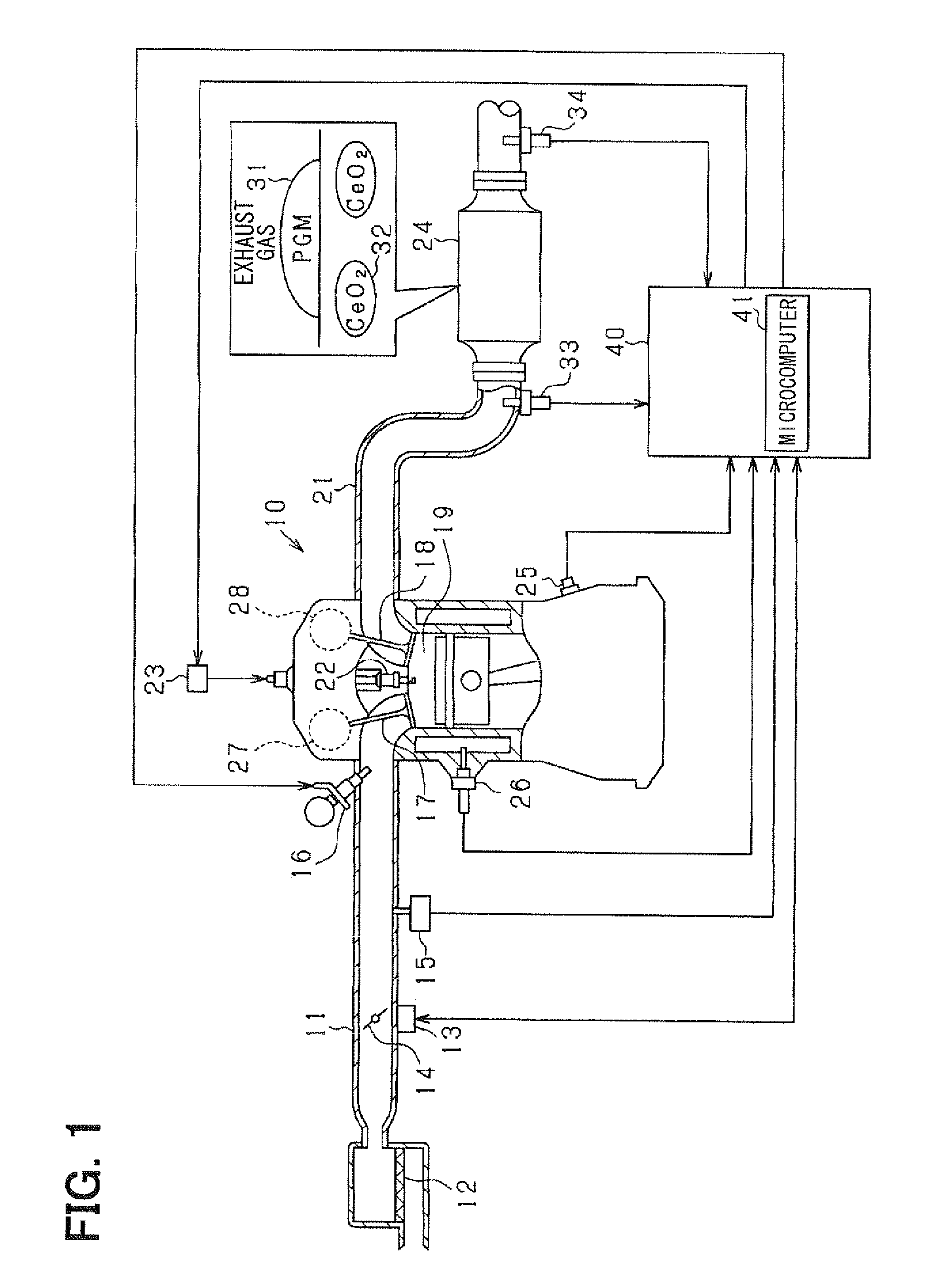
[0036]The first embodiment of the present invention will be described below with reference to the accompanying drawings. The present embodiment constitutes an engine control system for a gasoline engine for a vehicle. The control system mainly has an electronic control unit (hereinafter, referred as ECU) that controls a fuel injection quantity and controls ignition timing. FIG. 1 is a diagram illustrating an entire schematic structure of the engine control system.

[0037]In FIG. 1, an engine 10 is provided with an intake pipe 11 (intake passage), and an air cleaner 12 is provided at an upstream end of the intake pipe 11. A throttle valve 14 is provided downstream of the air cleaner 12, and an opening of the throttle valve 14 is adjusted by a throttle actuator 13, such as a DC motor. The opening of the throttle valve 14 (throttle opening) is detected by a throttle opening sensor included in the throttle actuator 13. Also, an intake pipe pressure sensor 15 is provided ...

second embodiment

(Second Embodiment)

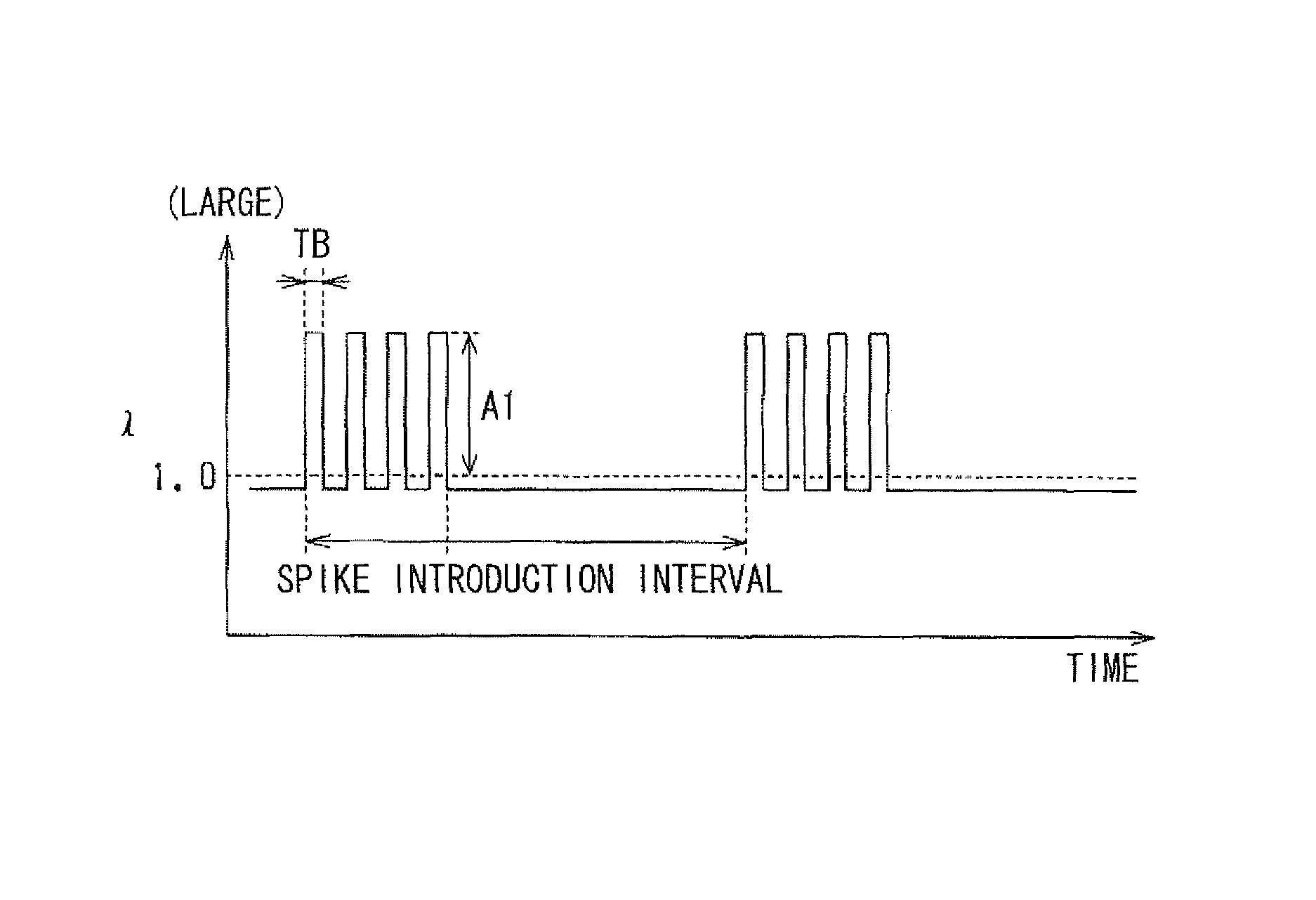
[0093]Next, the second embodiment of the present invention will be described mainly focusing on the difference from the first embodiment. In the present embodiment, as shown in FIG. 11, the air-fuel ratio is controlled at slightly rich, and also the lean spike operation is intermittently executed under the above conditioned slightly fuel-rich atmosphere. In addition to the above, rich inputs (RF, RB), which corresponds to the introduction of fuel-richer gas, are executed immediately before and immediately after the lean spike operation. The rich input RF immediately before the lean spike operation and the rich input RB immediately after the lean spike operation will be described with reference to accompanying drawings.

(Rich Input Immediately Before Lean Spike Operation)

[0094]In general, O2 is more likely to adsorb to the precious metal 31 than NOx absorbs to the precious metal 31. In other words, O2 has stronger absorption force to the precious metal 31 than absor...


PUM


Abstract

An exhaust gas purifying apparatus for an internal combustion engine includes a lean control unit and a rich control unit. The lean control unit executes lean spike operation, in which an air-fuel ratio is temporarily changed in a lean direction by a lean change width relative to a reference air-fuel ratio. The rich control unit changes the air-fuel ratio in a rich direction by a rich change width relative to the reference air-fuel ratio after the lean control unit executes the lean spike operation such that the air-fuel ratio stays in a predetermined slightly rich region. The rich change width is smaller than the lean change width.

Description

CROSS REFERENCE TO RELATED APPLICATION[0001]This application is based on and incorporates herein by reference Japanese Patent Application No. 2009-86480 filed on Mar. 31, 2009.BACKGROUND OF THE INVENTION[0002]1. Field of the Invention[0003]The present invention relates to an exhaust gas purifying apparatus for an internal combustion engine.[0004]2. Description of Related Art[0005]Conventionally, a three-way catalytic converter has been known to purify HC, CO, and NOx in exhaust gas of an internal combustion engine. The three-way catalytic converter mainly includes a precious metal, an element, and a oxygen storage medium. The precious metal serves as a catalyst composition, and the element, such as alumina, is used to disperse the precious metal. The oxygen storage medium stores and releases oxygen in exhaust gas.[0006]The three-way catalytic converter functions as an oxygen storage that stores oxygen in exhaust gas by using the oxygen storage medium, and the oxygen storage function...

Claims


Application Information

Patent Timeline
Patent Type & Authority Patents(United States)
IPC IPC(8): F02D41/00F01N3/00F01N3/08F01N3/20F02D41/02F02D41/14
CPCF02D41/1441F02D41/0295F02D41/1475F01N3/0871F01N3/20F02D2200/0814
Inventor YONEKAWA, YUTAKANAKANO, TOMOAKI
Owner DENSO CORP
Learn More