Slewing bearing and rotating section support device for wind turbine

a technology of rotating section and support device, which is applied in the direction of rotary machine parts, machines/engines, mechanical equipment, etc., can solve the problems of radial load and moment load of the bearing assembly used in the wind powered turbine, and achieve the effect of suppressing the cost of molds or the like, reducing the cost of manufacture, and reducing the occurrence of voids

Inactive Publication Date: 2015-02-03
NTN CORP
View PDF34 Cites 7 Cited by
  • Summary
  • Abstract
  • Description
  • Claims
  • Application Information

AI Technical Summary

Benefits of technology

[0009]Since the spacer has its dimensions determined for the ball size, it can be concurrently used with various bearing sizes regardless of the ball PCD. For this reason, it is possible to suppress additional expenses such as, for example, a mold cost. Hitherto, the retainer type used in the slewing bearing assembly for use in a construction machinery and a crane is a spacer type made of a resinous material.
[0016](2) Separation and collection, collection and distribution apt to occur easily relative to the retainer type.
[0018]An object of the present invention is to provide a slewing bearing assembly, which is effective to suppress additional costs such as, for example, a mold cost, and to resolve the problem associated with the insufficient strength brought about by the presence of voids, and also to provide a rotation section support apparatus for the wind powered turbine.
[0020]According to the construction described above, since the resinous material of the spacer is chosen to be of a kind having a melt viscosity not lower than 1000 Pa·s (270° C. in temperature), an undesirable occurrence of voids in a surface and / or inside of the spacer can be suppressed even through the spacer has a thick wall. Accordingly, it is possible to prevent the spacer from having an insufficient strength. Since the spacer has its dimensions determined in dependence on the ball size, it can be concurrently used with various bearing sizes regardless of the ball PCD. For this reason, the additional costs of the mold cost or the like can be suppressed. Therefore, it is possible to reduce the cost of manufacture of the slewing bearing assembly. Also, since it is a four point contact ball bearing, in which the ball is held in contact with an inner surface of a raceway groove in inner and outer rings at four locations, it is possible to load an axial load in both directions.
[0021]In one embodiment of the present invention, the spacer may have opposite sides formed with ball contact surfaces each having a recessed shape recessed deeply towards a center portion and a gate position of a mold assembly for injection molding the spacer is arranged at a bottom portion of the recessed shape. If, for example, the gate position of the mold assembly is arranged in an outer diametric portion of the spacer, it occurs quite often that the rage of occurrence of the voids becomes high and a bias occurs in the strength in a circumferential direction of the spacer (a condition after the bearing assembly has been incorporated). In contrast thereto, arranging the gate position of the mold at a bottom portion of the recessed surface shape referred to above, it is possible to reduce the rate of occurrence of the voids and also to avoid the occurrence of the bias in the strength in the circumferential direction of the spacer. The spacer is such that the ball contact surface on opposite sides thereof is rendered to represent a concaved surface shape depressed deep towards a center portion thereof, and, with a depression recessed deeper than the recess defined at a center portion of the recess, the gate position of the mold assembly used to injection mold the spacer may be provided in that depression.
[0023]Each of the balls may have a diameter within the range of 30 to 80 mm. In the case of the spacer used with the ball of such a diametric dimension, it becomes a thick walled produce larger than that of the spacer used with the balls of a diameter not greater than 30 mm. Even with the spacer representing such a thick walled product, the occurrence of the voids in the surface and / or inside of the spacer is suppressed and the possibility of having an insufficient strength can be avoided since the resinous material of the spacer is chosen to be of a kind having a melt viscosity of 1000 Pa·s (270° C. in temperature) or higher.

Problems solved by technology

The slewing bearing assembly used in the wind powered turbine is susceptible to a radial load and a moment load in addition to an axial load.

Method used


Image

  • Slewing bearing and rotating section support device for wind turbine
  • Slewing bearing and rotating section support device for wind turbine
  • Slewing bearing and rotating section support device for wind turbine

Examples


first embodiment

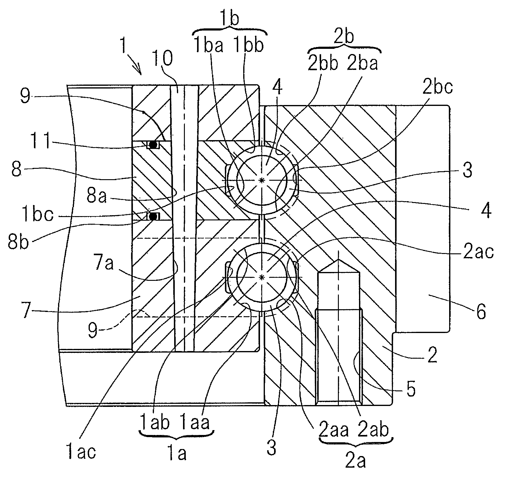
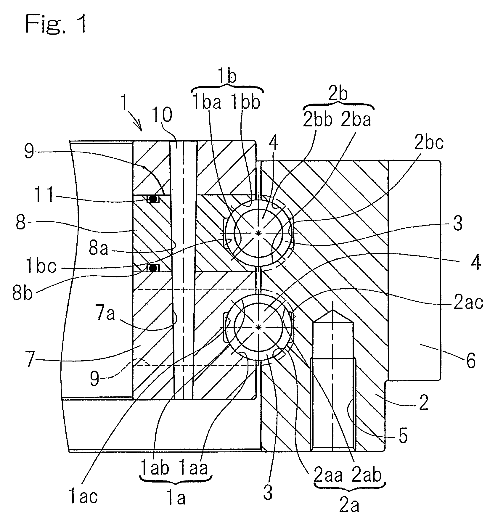
[0039]the present invention will now be described in detail with particular reference to FIGS. 1 to 7. A slewing bearing assembly shown therein is used as a bearing assembly in, for example, rotatably supporting, relative to a main shaft, a wind mill of a wind powered turbine for rotation about an axis substantially perpendicular to an axis of the main shaft or in supporting a nacelle of the wind powered turbine relative to a support post.

[0040]Referring to FIG. 1, the slewing bearing assembly includes an inner ring 1 having defined therein a plurality of, for example, two, raceway grooves 1a and 1b, an outer ring 2 having defined therein a corresponding number of raceway grooves 2a and 2b, and corresponding rows of balls 3, one row rollingly interposed between the raceway grooves 1a and 2a and the other row rollingly interposed between the raceway grooves 1b and 2b, and a spacer 4 interposed between the neighboring balls 3 of each of the ball rows. Each of the raceway grooves 1a, 1...

second embodiment

[0063]Now with particular reference to FIG. 8, the spacer for the slewing bearing assembly will be described in detail. As shown therein, each of the ball contact surfaces 4a and 4a on the respective sides of the spacer 4 may be of a composite curved shape comprised of a contact surface radially inner portion 4aa and a contact surface radially outer portion 4ab, which are in the form of a curved surface of a rotated body depicted when two arches having a center curvature and a curvature center different from each other are rotated 360°.

[0064]More specifically, the contact surface radially inner portion 4aa is of a shape having a spherical portion of a diameter substantially equal to the radius R of each of the balls (See FIG. 3) as a ball contact portion. Instead of the ball contact surfaces 4a and 4a of the composite curved shape as described above, the spacer 4 may be so shaped that the ball contact surfaces 4a and 4a on the respective sides thereof are of a single conical surfac...


PUM

PropertyMeasurementUnit
diameteraaaaaaaaaa
temperatureaaaaaaaaaa
melt viscosityaaaaaaaaaa

Abstract

A slewing bearing assembly effective to suppress additional expenses such as a mold cost and to resolve the problem associated with insufficient strength brought about by voids and, also, a rotation section support apparatus for a wind powered turbine are provided. The slewing bearing assembly includes inner and outer rings having raceway grooves, and a plurality of balls interposed between the raceway grooves, and a spacer interposed between the neighboring balls. This slewing bearing assembly is a four point contact ball bearing, in which respective sectional shapes of the raceway grooves are so shaped as to represent shapes in which each balls contacts inner surfaces of the raceway grooves in the inner and outer rings at four points. The spacer is made of a resinous material having a melt viscosity within the range of 1000 to 2000 Pa·s at a temperature of 270° C.

Description

CROSS REFERENCE TO RELATED APPLICATIONS[0001]This application claims the benefit under 35 U.S.C. Section 371, of PCT International Application No. PCT / JP2010 / 062165, filed Jul. 20, 2010, which claimed priority to Japanese Application No. 2009-174261, filed Jul. 27, 2009 in the Japanese Patent Office, the disclosures of which are hereby incorporated by reference.BACKGROUND OF THE INVENTION[0002]1. Field of the Invention[0003]The present invention relates to a slewing bearing assembly, which is used in a rotation section for yaw and a wind mill of a wind powered turbine and in a deck crane as a slewing pedestal and also to a rotation section support apparatus for the wind powered turbine.[0004]2. Description of Related Art[0005]A slewing bearing assembly is currently employed in a rotation section or the like for yaw and a wind mill of the wind powered turbine (a wind powered, electricity generating turbine). In the wind powered turbine, need is generally recognized to change the angl...

Claims


Application Information

Patent Timeline
Patent Type & Authority Patents(United States)
IPC IPC(8): F16C43/06F16C19/20F16C33/58F03D7/02F03D11/00F16C19/18F16C33/37
CPCF03D7/0204F03D11/0008F16C19/181F16C19/20F16C33/3706F16C2300/14Y02E10/722Y02E10/726Y02E10/723F16C2360/31F03D80/70F16C2208/60F16C2210/04F16C2220/04Y02E10/72F05B2240/50
Inventor HORI, MICHIOKUWAHARA, NURUMU
Owner NTN CORP
Why Eureka
Try Eureka