
Method and apparatus for concentrating ozone gas

a technology of concentrating equipment and ozone gas, which is applied in the direction of separation processes, chemical/physical/physical/physical-chemical processes, energy-based chemical/physical/physical-chemical processes, etc., can solve the problems of unstable supply-concentration of ozone, increased pressure in concentrated ozone extraction pipes, and further decreased concentration thereof. , to achieve the effect of rapid pressure increase, rapid pressure increase, and high internal pressur

Active Publication Date: 2015-02-03
IWATANI CORP
View PDF9 Cites 0 Cited by
  • Summary
  • Abstract
  • Description
  • Claims
  • Application Information

AI Technical Summary

Benefits of technology

[0009]The present invention has been made in view of the above problem. An object of the present invention is to provide a method and an apparatus for concentrating ozone gas with simple additional pipes and piping instruments, which are capable of preventing the rapid pressure increase in the apparatus immediately after the desorption of ozone gas starts, and extracting concentrated ozone gas at a higher concentration ratio by increasing adsorption pressure.
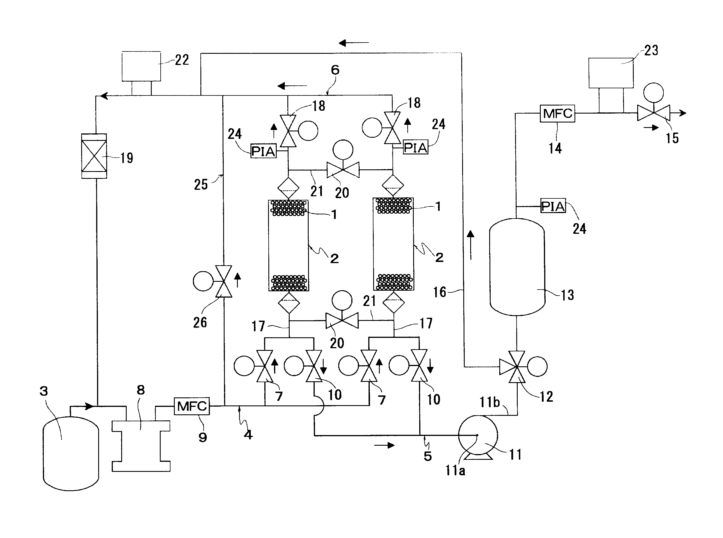
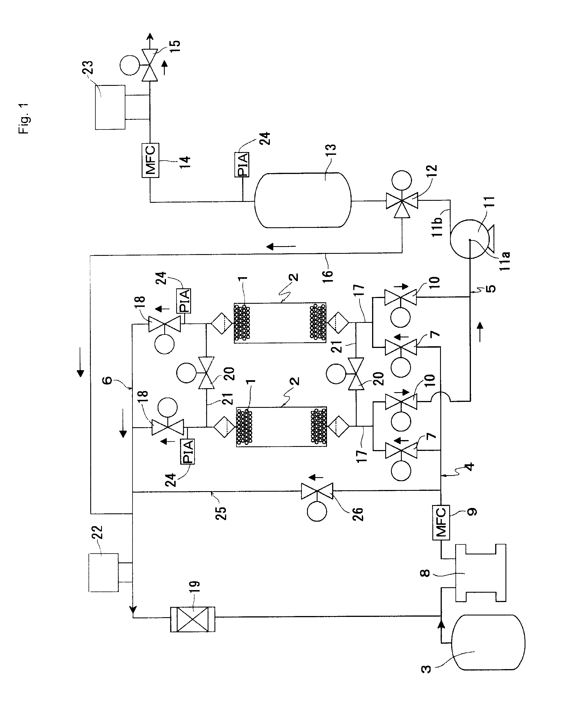
[0012]According to a third aspect of the present invention, a valve placed on an ozone gas inlet side of one of the adsorbing cylinders that has performed the adsorption step is closed while a valve placed on an outlet side thereof is opened, immediately before the pressure equalization step starts, so that an internal pressure of the one of the adsorbing cylinders is decreased.
[0014]In the present invention, the pressure equalization causes a higher internal pressure in each adsorbing cylinder after the adsorption to be decreased to substantially the atmospheric pressure. This prevents the rapid pressure increase in pipes and the decompression generation section immediately after the desorption starts. Also, this prevents ozone gas from self-decomposing and any instrument from being damaged due to the rapid pressure increase. Consequently, it is possible to increase the adsorption pressure in each adsorbing cylinder, thereby increasing the concentration ratio of ozone gas, as well as to decompress the interior of each adsorbing cylinder by directly applying the attraction power of the decompression generation section to the interior, thereby increasing the extraction amount of ozone gas.
[0015]Furthermore, the communication passages that cause the interiors of the adsorbing cylinders to communicate with one another are positioned closer to the adsorbing cylinders than the valves attached to gas passages communicating with the adsorbing cylinders, and the passage open / close valves are simply attached to these communication passages. Accordingly, it is possible to further increase the concentration of ozone gas without the need to add many instruments and greatly enlarge an installation space, simply by adding simple pipes and pipe instruments.

Problems solved by technology

In addition, due to its great self-decomposability, ozone gas is self-decomposing while flowing through an ozone gas supply route.
At a stage where the ozone gas is supplied to ozone gas consumption equipment, a concentration thereof is further decreased and the supply-concentration thereof is unstable by nature.
However, when ozone gas is adsorbed at high pressure, the pressure increases rapidly in the concentrated ozone extraction pipe immediately after the desorption starts.
Therefore, it seems difficult to increase the adsorbed amount, simply by increasing the pressure.
Although it is possible to prevent the rapid pressure increase in the derivation passage for desorbed ozone gas immediately after the desorption of the ozone gas starts, the performance of the decompression generation section cannot be exerted on the desorption operation of ozone gas which is carried out by the adsorbing cylinder.
Accordingly, the desorption pressure does not decrease sufficiently, thereby failing to concentrate ozone gas appropriately.

Method used


Image

  • Method and apparatus for concentrating ozone gas
  • Method and apparatus for concentrating ozone gas
  • Method and apparatus for concentrating ozone gas

Examples


example 1

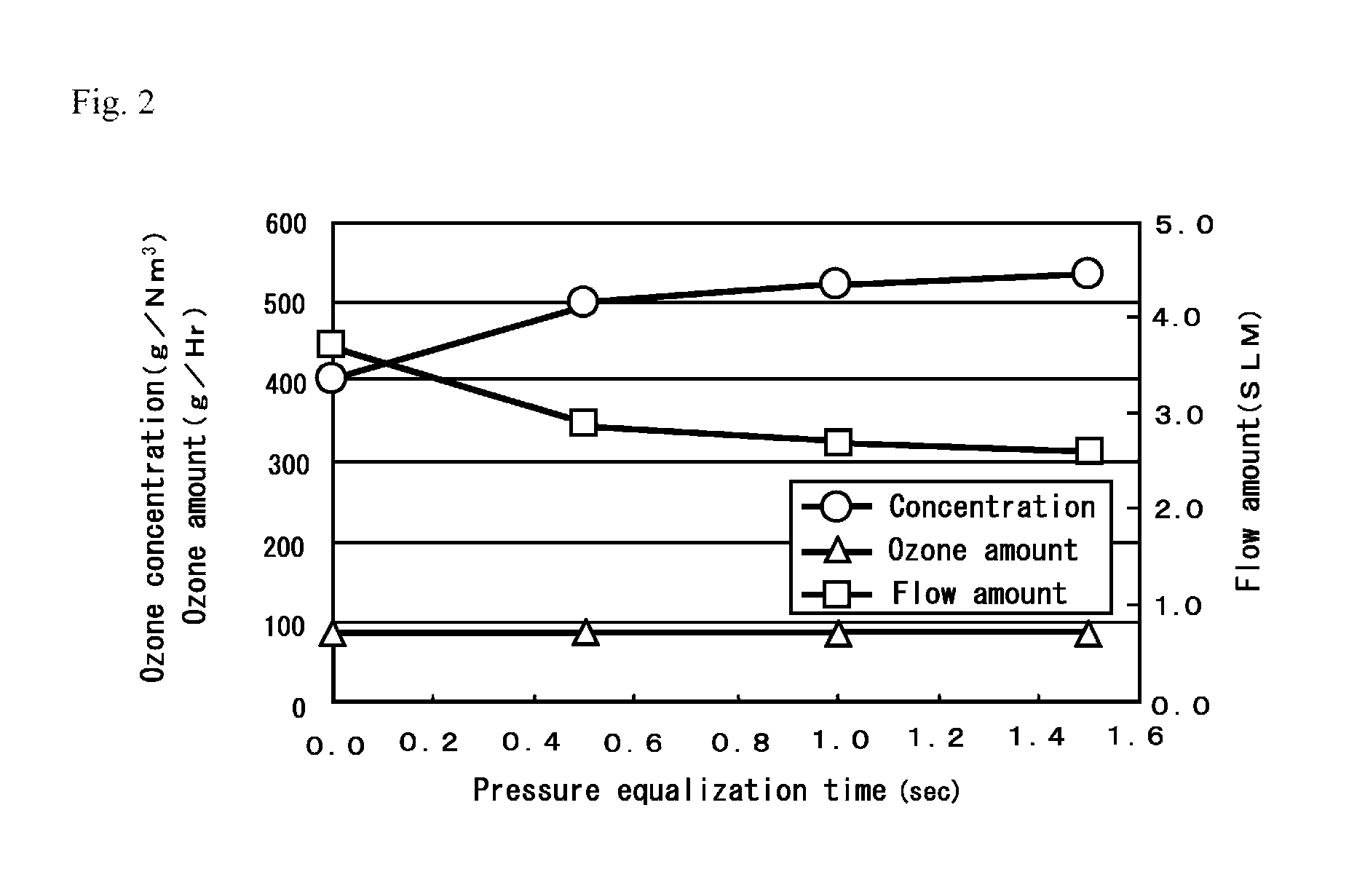
[0034]The two adsorbing cylinders 2 with an internal volume of 1 liter, in each of which highly pure silica gel of 650 grams was filled as the ozone gas adsorbent 1, were arranged parallel to each other. The parts of the gas discharge passage 6 connected to both adsorbing cylinders 2 and 2 communicated with each other through a communication passage 21 having a bore of ⅜ inches. Likewise, the parts of the joint passage 17 connected to both adsorbing cylinders 2 communicated with each other through the communication passage 21 having a bore of ⅜ inches. Then, ozone-oxygen mixture gas was supplied to each adsorbing cylinder 2 through the gas introduction passage 4 with a supply amount of 14.71 slm, and the apparatus was operated under the condition that an adsorption pressure was 100 kPa·G and ultimate pressure upon desorption was −90 kPa·G in each absorbing cylinder 2. Further, the ozone was concentrated under the condition that pressure equalization steps were 0, 0.5, 1, and 1.5 sec...

example 2

[0043]Similar to Example 1 described above, the two adsorbing cylinders 2 with an internal volume of 1 liter, in each of which highly pure silica gel of 650 grams was filled as the ozone gas adsorbent 1, were arranged parallel to each other. The parts of the gas discharge passage 6 connected to both adsorbing cylinders 2 communicated with each other through a communication passage 21 having a bore of ⅜ inches. Likewise, the parts of the joint passage 17 connected to both adsorbing cylinders 2 communicated with each other through the communication passage 21 having a bore of ⅜ inches. Then, ozone-oxygen mixture gas was supplied to the adsorbing cylinders 2 through the gas introduction passage 4 with a supply amount of 14.71 slm, and the apparatus was operated under the condition that an adsorption pressure was 100 kPa·G and ultimate pressure upon desorption was −90 kPa·G in each absorbing cylinder 2. An adsorption-desorption switching cycle was set to 40 seconds. Then, a gas introduc...


PUM

PropertyMeasurementUnit
internal volumeaaaaaaaaaa
concentration ratioaaaaaaaaaa
pressureaaaaaaaaaa

Abstract

A method of concentrating ozone gas including: causing ozone gas contained in ozone-oxygen mixture gas to be selectively adsorbed to adsorbents which are filled in a non-cooled state in at least two adsorbing cylinders arranged parallel to one another; desorbing the ozone gas from the adsorbents by subjecting a depressurizing process to each adsorbing cylinder during an ozone gas desorption operation; repeating an adsorption step and a desorption step alternately in the at least two adsorbing cylinders; and controlling the adsorbing cylinders, in such a way that one of the adsorbing cylinders is performing the adsorption step while another one of the adsorbing cylinders is performing the desorption step.

Description

BACKGROUND OF THE INVENTION[0001](1) Field of the Invention[0002]The present invention relates to a method and an apparatus for supplying ozone gas concentrated within a predetermined concentration range to ozone consumption equipment such as semiconductor manufacturing equipment. More particularly, the present invention relates to a method and an apparatus for purifying ozone gas generated by an ozone generator (ozonizer) and supplying the purified ozone gas as an ozone gas concentrated within a predetermined concentration range.[0003](2) Description of Related Art[0004]Generally, ozone gas is generated by supplying oxygen gas from an oxygen tank or separated from the atmosphere to an ozone generator. However, even when ozone gas is generated by using oxygen gas from an oxygen tank, the generated ozone gas contained in the oxygen gas has a concentration of as low as approximately 5 vol % to 10 vol %. In addition, due to its great self-decomposability, ozone gas is self-decomposing ...

Claims


Application Information

Patent Timeline
Patent Type & Authority Patents(United States)
IPC IPC(8): B01D53/047C01B13/10
CPCB01D53/047C01B13/10B01D2253/106B01D2256/14B01D2259/40007B01D2259/40035B01D2259/402B01D53/02B01J20/00
Inventor MAKIHIRA, NAOHISANAKAMURA, SADAKIINOUE, GOICHIKOIKE, KUNIHIKO
Owner IWATANI CORP
Learn More