Variable reluctance type angle sensor
a technology of resistance type and angle sensor, which is applied in the direction of instruments, measuring devices, coils, etc., can solve the problems of complex structure of the sensor, and achieve the effect of simple structur
- Summary
- Abstract
- Description
- Claims
- Application Information
AI Technical Summary
Benefits of technology
Problems solved by technology
Method used
Image

Examples
first embodiment
[0026]A first embodiment of the present invention will now be described with reference to the drawings.
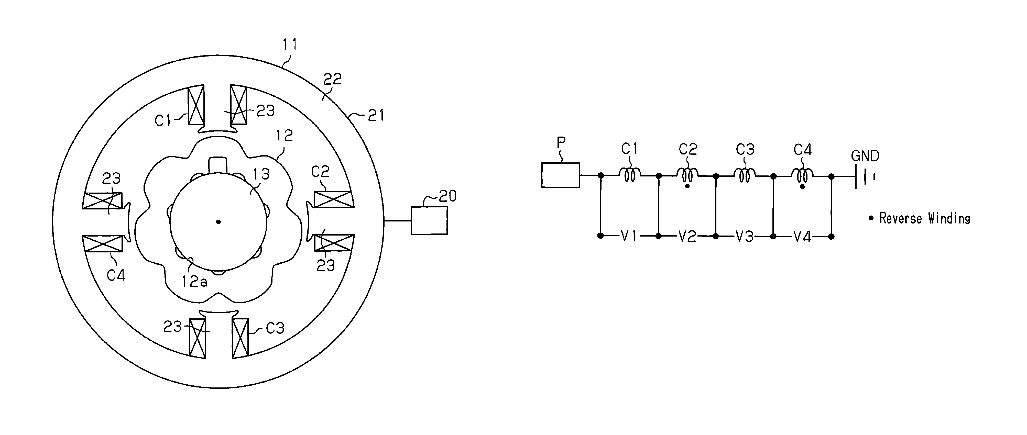
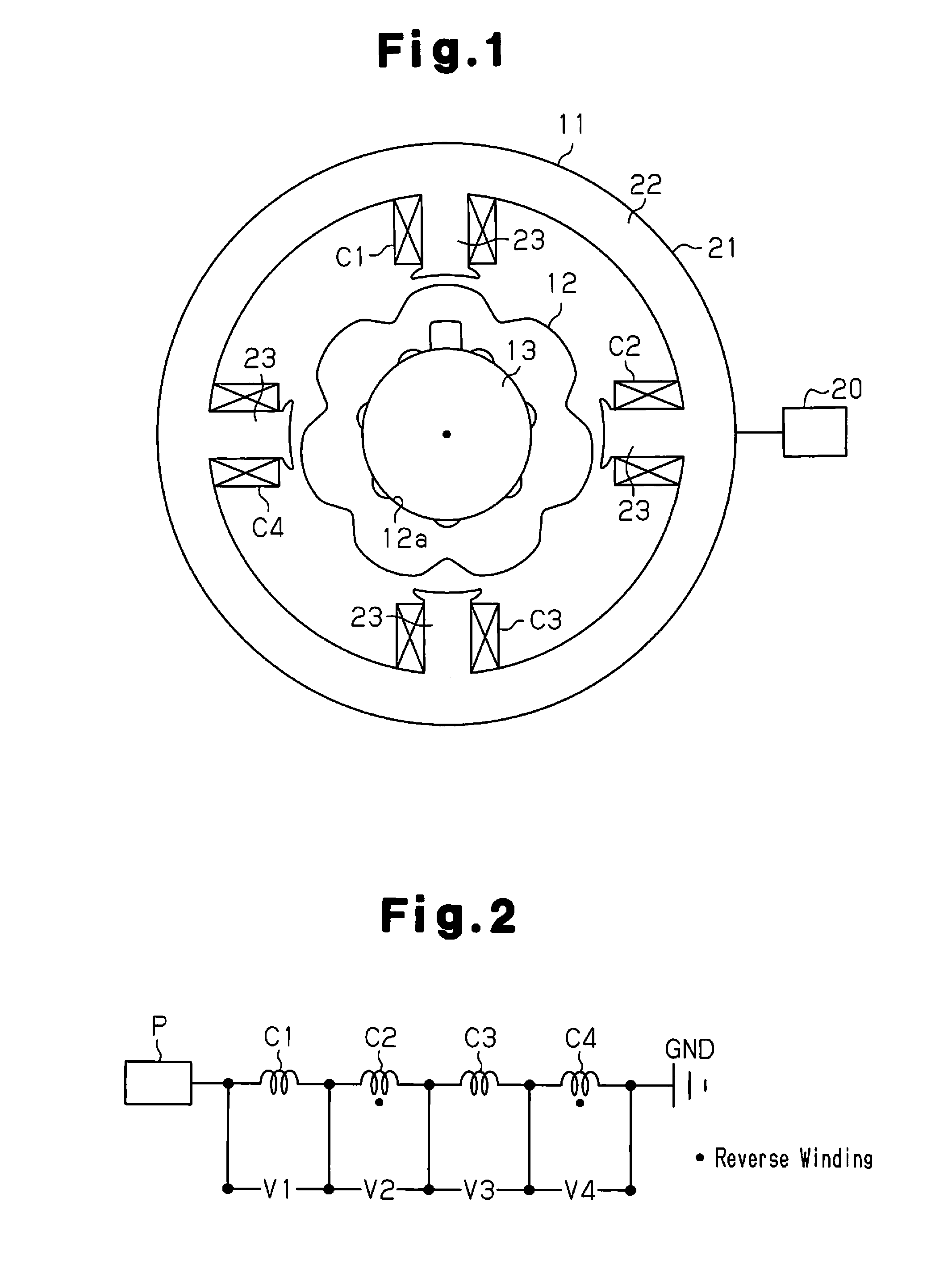
[0027]As shown in FIG. 1, a variable reluctance type angle sensor of the first embodiment includes an annular stator 11 and a rotor 12, which is rotationally mounted on the inner circumference of the stator 11.
[0028]For example, a rotary shaft 13 of a motor is press-fitted in a mounting hole 12a formed at the center of the rotor 12, and the rotor 12 rotates integrally with the rotary shaft 13. Recesses and protrusions are formed on the outer circumferential surface of the rotor 12 in the circumferential direction. Due to the recesses and the protrusions, the rotor 12 has such a shape that gap permeance with respect to the stator 11 varies in a sinusoidal fashion in accordance with the rotation electrical angle θ of the rotor 12. In the rotation electrical angle θ, one cycle of sinusoid signal generated by the rotor 12 is defined as 360 degrees. In the present invention, an interval...
second embodiment
[0046]In the first embodiment, the number of the teeth 23 and the number of the excitation coils (the coils C1 to C4) is four each, and the multiplication factor of angle of the rotor 12 is seven, which forms a variable reluctance type angle sensor of 4s7×. A second embodiment provides a variable reluctance type angle sensor of 8s7× as shown in FIG. 6.
[0047]As shown in the drawing, first to eighth coils C1 to C8 are wound about eight teeth 23 located at circumferentially equal intervals (315 degree intervals in terms of the electrical angle, 45 degree intervals in terms of the mechanical angle) clockwise in this order. The first to eighth coils C1 to C8 are formed by winding a single conductive wire about the teeth 23 continuously by concentrated winding. That is, the first to eighth coils C1 to C8 are connected in series as shown in FIG. 7. Also, like the first embodiment, the winding direction of the coils C1 to C8 is alternately reversed in the circumferential direction, and the ...
third embodiment
[0052]A third embodiment provides a variable reluctance type angle sensor of 12s7× as shown in FIG. 9.
[0053]As shown in the drawing, first to twelfth coils C1 to C12 are wound about twelve teeth 23 located at equal intervals in the circumferential direction (30 degree intervals in terms of the mechanical angle) clockwise in this order. The first to twelfth coils C1 to C12 are formed by winding a single conductive wire continuously about the teeth 23 by concentrated winding. That is, the first to twelfth coils C1 to C12 are connected in series as shown in FIG. 10. Also, like the first embodiment, the winding direction of the coils C1 to C12 is alternately reversed in the circumferential direction, and the circumferentially adjacent coils have different polarities from each other. Furthermore, the number of windings of the first to twelfth coils C1 to C12 is set all equal.
[0054]In the third embodiment, the first excitation coil group includes the first, second, sixth, seventh, eighth,...
PUM
 Abstract
Description
Claims
Application Information
 - R&D
- Intellectual Property
- Life Sciences
- Materials
- Tech Scout
- Unparalleled Data Quality
- Higher Quality Content
- 60% Fewer Hallucinations
Browse by: Latest US Patents, China's latest patents, Technical Efficacy Thesaurus, Application Domain, Technology Topic, Popular Technical Reports.
© 2025 PatSnap. All rights reserved.Legal|Privacy policy|Modern Slavery Act Transparency Statement|Sitemap|About US| Contact US: help@patsnap.com